Agilent B1500A Semiconductor Device Analyzer Configuration and Connection Guide Agilent Technologies
Notices © Agilent Technologies, Inc. 2005-2013 Warranty No part of this manual may be reproduced in any form or by any means (including electronic storage and retrieval or translation into a foreign language) without prior agreement and written consent from Agilent Technologies, Inc. as governed by United States and international copyright laws. The material contained in this document is provided “as is,” and is subject to being changed, without notice, in future editions.
Contents 1. B1500A Product Configuration Product line up of the B1500A series . . . . . . . . . . . . . . . . . . . . . . . . . . . . . . . . . . 1-2 Options of B1500A series . . . . . . . . . . . . . . . . . . . . . . . . . . . . . . . . . . . . . . . . . . . 1-6 Furnished accessories. . . . . . . . . . . . . . . . . . . . . . . . . . . . . . . . . . . . . . . . . . . . . . 1-10 Upgrade products for the B1500A series . . . . . . . . . . . . . . . . . . . . . . . . . . . . . . .
Contents SMU connections. . . . . . . . . . . . . . . . . . . . . . . . . . . . . . . . . . . . . . . . . . . . . . . . Non-Kelvin connection . . . . . . . . . . . . . . . . . . . . . . . . . . . . . . . . . . . . . . . . . Kelvin connection. . . . . . . . . . . . . . . . . . . . . . . . . . . . . . . . . . . . . . . . . . . . . . Kelvin to non-Kelvin connection . . . . . . . . . . . . . . . . . . . . . . . . . . . . . . . . . . MCSMU connections. . . . . . . . . . . . . . . . . . . . . . . . . . . . . . .
1 B1500A Product Configuration
B1500A Product Configuration Product line up of the B1500A series 1.1 Product line up of the B1500A series The Agilent B1500A Semiconductor Device Analyzer is the new generation one box solution for the semiconductor device DC/AC parametric measurement and analysis application. Agilent B1500A provides the DC voltage/current output capability, DC voltage/current measurement capability, and AC signal output and impedance measurement capability.
B1500A Product Configuration Product line up of the B1500A series • MCSMU module (B1500A-A1A or A1B) 50 s pulse Medium current source/monitor unit module. Occupies one slot. • MFCMU module (B1500A-A20) Multi frequency capacitance measurement unit module. Occupies one slot. Needs Agilent N1301A-100 SCUU to perform automatic switching of the measurement resources connection. • HVSPGU module (B1500A-A25) High voltage semiconductor pulse generator unit module. Occupies one slot.
B1500A Product Configuration Product line up of the B1500A series • N1302A-200 GSWU Guard switch unit (GSWU). Needs the SCUU to use the GSWU. Effective for the accurate impedance measurements by connecting the guard lines between CMU high and low near the DUT. • B1542A pulsed IV package B1542A expands the capabilities of the B1500A to enable the ultra short pulsed IV measurements with parametric characterization down to 10 ns pulse width for many new device structures.
B1500A Product Configuration Product line up of the B1500A series Figure 1-1 B1500A Rear View Agilent B1500A Configuration and Connection Guide, Edition 5 1- 5
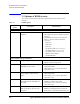
B1500A Product Configuration Options of B1500A series 1.2 Options of B1500A series This section describes Option items of the Agilent B1500A Semiconductor Device Analyzer. Table 1-3 Model/ Option B1500A Options Description OP Instruction Mainframe B1500A Semiconductor device analyzer mainframe • Select option 015 or 030 to specify cable length. • Select option 050 or 060 to specify Power line frequency. • The following accessories are included. See Table 1-3, for more details of furnished accessories.
B1500A Product Configuration Options of B1500A series Model/ Option Description OP Instruction Select add-on packages (optional) B1500A-A10 Add-on package - High power source monitor unit (B1510A) 1ea, cables • HPSMU add-on package adds one HPSMU and two triaxial cables. • Cable length 1.5 m or 3.0 m is specified by option 015 or 030. B1500A-A11 Add-on package - Mid power source monitor unit (B1511B) 1ea, cables • MPSMU add-on package adds one MPSMU and two triaxial cables. • Cable length 1.
B1500A Product Configuration Options of B1500A series Model/ Option Description OP Instruction B1500A-A30 Add-on package - WGFMU 1ea, Remote sense unit 2ea, cables • WGFMU add-on package adds one WGFMU, two RSU, and two RSU cables • Cable length 1.5 m or 3.0 m is specified by option 015 or 030. B1500A-A31 Add-on package - WGFMU 1ea, Connector adaptor, Remote sense unit 2ea, cables • WGFMU add-on package adds one WGFMU, two RSU, and accessories for connector plate. See Table 1-19. • Cable length 1.
B1500A Product Configuration Options of B1500A series Model/ Option B1500A-1CM Description Rack mount kit OP Instruction • Rack mount kit for the B1500A. • 7U height EIA Select WGFMU learning kit (optional) B1530A-0KN Self-paced sample program learning kit for B1530A WGFMU • This option becomes available when B1500A-A30 or A31 is selected.
B1500A Product Configuration Furnished accessories 1.3 Furnished accessories Furnished accessories of the B1500A semiconductor device analyzer and furnished accessories of package options are described in this chapter. Table 1-4 Description Furnished accessories on the B1500A semiconductor device analyzer mainframe Qty. Note USB keyboard 1 USB Keyboard for the B1500A USB mouse 1 USB Mouse for the B1500A Stylus pen 1 Stylus pen for the B1500A Interlock cable 1 Cable length 1.5 m or 3.
B1500A Product Configuration Furnished accessories Description Qty. Note GNDU Kelvin adapter 1 GNDU Kelvin adapter must be directly connected to the B1500A GNDU connector for taking out the GNDU Force and Sense to the individual connectors. Then the GNDU cable must be used for extending the GNDU Force. And the triaxial cable must be used for the Sense. Triaxial cable 1 Cable length 1.5 m or 3.0 m is specified by the option B1500A-015 or B1500A-030.
B1500A Product Configuration Furnished accessories Table 1-5 Description B1500A-A01 Standard Pack 1 -Standard package Qty. Note MPSMU 4 Installed Medium power source/monitor unit (MPSMU) Triaxial cable 8 Cable length 1.5 m or 3.0 m is specified by the option B1500A-015 or B1500A-030. Table 1-6 Description B1500A-A02 Standard Pack 2 -High resolution package Qty. Note HRSMU 4 Installed High resolution source/monitor unit (HRSMU) Triaxial cable 8 Cable length 1.5 m or 3.
B1500A Product Configuration Furnished accessories Description Qty. Note 16440A pulse selector 1 16440A SMU/PGU pulse generator selector 16445A Selector adapter 1 16445A Selector adapter for 16440A Control cable, 1.5 m 1 Digital I/O cable, 1.5 m, between B1500A and 16445A (16445A-001) Control cable, 40 cm 1 Control cable, 40 cm, between 16445A and 16440A (16440A-003) Triaxial cable, 1.5 m 2 Cable length 1.5 m for 16440A pulse selector. Triaxial cable 8 Cable length 1.5 m or 3.
B1500A Product Configuration Furnished accessories Table 1-11 Description B1500A-A17 Add-on Package - High resolution source monitor unit Qty. Note HRSMU 1 Installed High resolution source/monitor unit (HRSMU) Triaxial cable 2 Cable length 1.5 m or 3.0 m is specified by the option B1500A-015 or B1500A-030. Table 1-12 Description B1500A-A1A Add-on Package - 50 s Pulse Medium current source monitor unit Qty.
B1500A Product Configuration Furnished accessories Table 1-14 Description B1500A-A20 Add-on Package - Capacitance measurement unit Qty. Note MFCMU 1 Installed Multi frequency capacitance measurement unit (MFCMU) CMU cable 1 CMU Cable for B1500 (N1300A). Cable length 1.5 m or 3.0 m is specified by the option B1500A-015 or B1500A-030. Table 1-15 Description B1500A-A25 Add-on Package - Pulse generator unit Qty.
B1500A Product Configuration Furnished accessories Table 1-16 B1500A-A28 Add-on Package - Atto sense unit for HRSMU Description Qty. Note ASU 1 Atto sense switch unit (E5288A ASU), 1 ea. Triaxial and D-sub cable for ASU 1 Triaxial/D-sub Cable for ASU (16493M). Cable length 1.5 m or 3.0 m is specified by the option B1500A-015 or B1500A-030. Table 1-17 B1500A-A29 Add-on Package - Atto sense unit for MPSMU Description Qty. Note ASU 1 Atto sense switch unit (E5288A ASU), 1 ea.
B1500A Product Configuration Furnished accessories Table 1-18 Description B1500A-A30 Add-on Package - WGFMU and RSU Qty. Note WGFMU 1 Installed Waveform generator/fast measurement unit (WGFMU) RSU 2 Remote-sense and switch unit (RSU) RSU cable 2 RSU cable between WGFMU and RSU. Cable length 1.5 m or 3.0 m is specified by the option B1500A-015 or B1500A-030. Table 1-19 Description B1500A-A31 Add-on Package - WGFMU, RSU and connecter adapter Qty.
B1500A Product Configuration Furnished accessories Table 1-20 B1500A-A3P Add-on Package - Probe cable kit for WGFMU Description Qty.
B1500A Product Configuration Furnished accessories Table 1-21 B1500A-A5F Add-on Package - Test fixture for packaged device Description Qty. Note Test fixture 1 Test fixture for packaged device (16442B) Accessory case 1 Accessory case for furnished accessories. Blank PTFE board 1 Blank PTFE board for DUT stage 28-pin socket module 1 28-pin DIP (dual-in-line) package socket module Universal socket module 1 Universal socket module, 0.
B1500A Product Configuration Upgrade products for the B1500A series 1.4 Upgrade products for the B1500A series The Agilent B1500A has 10 slots so that users can install appropriate modules into mainframe. The upgrade/retrofit product is available to add more modules. These modules should be installed in Agilent Technologies service center to meet the specifications. 1.4.1 Option of B1500AU upgrade kit The following table lists the upgrade products and related accessories.
B1500A Product Configuration Upgrade products for the B1500A series Model/Option Description OP Instruction B1500AU-089 Addition of E5288A Atto sense and switch unit (ASU. B1511B MPSMU is required.) 0.1 fA (100 aA) resolution which is used with B1511B MPSMU. 1 Triaxial, 2 BNC input ports and 1 communication D-sub input between ASU and SMU. BNC inputs terminal can be used for CMU, PGU or other instrument.
B1500A Product Configuration Upgrade products for the B1500A series Model/Option Description OP Instruction B1500AU-W03 5m Cable between WGFMU and RSU (2ea) WGFMU-to-RSU cable, 5 m (2 ea) B1500AU-W04 0.6m/4.4m Cable set between WGFMU and RSU(2ea). Require prober I/F with adapter WGFMU-to-RSU cable, 0.6 m / 4.4 m Cable set (2 ea). This option requires prober I/F and connection adapter. B1500AU-W05 1.5m Cable between WGFMU and RSU (2ea) WGFMU-to-RSU cable, 1.
B1500A Product Configuration Upgrade products for the B1500A series Model/Option Description OP Instruction B1500AU-PB1 Frame PS Upgrade It is required Frame Power Supply upgrade depended on the configuration and serial number. Contact Agilent Technologies to upgrade the B1500A. B1500AU-PB2 Power PC Board Upgrade It is required Power PC Board upgrade depended on the configuration and serial number. Contact Agilent Technologies to upgrade the B1500A.
B1500A Product Configuration Upgrade products for the B1500A series 1.4.2 About Plug-in modules Agilent Technologies is responsible for the module installation of Agilent B1500A. Contact Agilent Technologies for the module installation. Then send the following equipment and accessories to Agilent Technologies.
B1500A Product Configuration Upgrade products for the B1500A series 1.4.3 Module type and locations Module locations when the B1500A is shipped from the factory are shown in Table 1-24. This table shows the relative locations by the module types. If the SPGUs are installed, the SPGUs must be installed in the slots from the slot number 1. And if the SPGU and the WGFMU are not installed and the HPSMUs are installed, the HPSMUs must be installed in the slots from the slot number 1.
B1500A Product Configuration Upgrade products for the B1500A series 1.4.4 Maximum Module Configuration The B1500A can contain any combination of the following module. Then the total power consumption of all SMU modules cannot exceed 84 W. • Up to 10 MPSMU • Up to 10 HRSMU • Up to 4 HPSMU • Up to 4 MCSMU • One MFCMU • Up to 5 HVSPGU • Up to 5 WGFMU 1.4.5 Limitation by installing B1500AU-030 WGFMU The following tables show the limitation of installing WGFMU and additional SMU/CMU/HVSPGU.
B1500A Product Configuration EasyEXPERT and Desktop EasyEXPERT software 1.5 EasyEXPERT and Desktop EasyEXPERT software This section describes Agilent EasyEXPERT software and related options. For technical details of EasyEXPERT software and Desktop EasyEXPERT software, refer to data sheet of B1500A or www.agilent.com/find/easyexpert web site. 1.5.1 Functions and capabilities Agilent EasyEXPERT software is a specially-designed Windows application program for controlling Agilent B1500A.
B1500A Product Configuration EasyEXPERT and Desktop EasyEXPERT software • Quick test mode - A GUI-based quick test mode enables you to perform test sequencing without programming. You can select, copy, rearrange, and cut-and-paste any test setups with a few simple mouse clicks. Once you have selected and arranged your tests, simply click on the measurement button to begin running an automated test sequence.
B1500A Product Configuration EasyEXPERT and Desktop EasyEXPERT software Workspace and data management EasyEXPERT has separate work environment (Workspace). Every workspace supports the following features.
B1500A Product Configuration EasyEXPERT and Desktop EasyEXPERT software 1.5.2 Desktop EasyEXPERT Software Agilent Desktop EasyEXPERT is the same software that is built-in to the PC-based Agilent B1500A Semiconductor Device Analyzer, except that it runs on a standalone PC. In addition, Desktop EasyEXPERT supports Offline mode and control capability of the following 4155 series. NOTE The latest revision of Desktop EasyEXPERT software is available on the “www.agilent.com/find/easyexpert” web site.
B1500A Product Configuration EasyEXPERT and Desktop EasyEXPERT software 1.5.3 System requirements The following table shows the minimum requirements to run the Desktop EasyEXPERT or other software/program furnished with the B1500A. They are effective as of June 2013. For the latest information, go to www.agilent.com and type in EasyEXPERT in the Search field at the top of the page.
B1500A Product Configuration EasyEXPERT and Desktop EasyEXPERT software 1.5.4 License Management Tool The licence management tool is the program used to install the license of the software listed below. This program is also used to confirm the licenses already installed and the host ID of the B1500 or the computer for Desktop EasyEXPERT.
B1500A Product Configuration EasyEXPERT and Desktop EasyEXPERT software NOTE How to get the SWS Extension. The latest B1500A includes the license for SWS Extension. However, if you use old revision of EasyEXPERT and upgrade to revision 5.5 or later, the B1500AU upgrade kit with SWS option is required. Contact Agilent Technologies to upgrade the B1500A. NOTE How to get the license file (.lic file) for SWS Extension. The license file (.
B1500A Product Configuration B1542A Pulsed IV package for B1500A 1.
B1500A Product Configuration B1542A Pulsed IV package for B1500A The B1542A does not contain Oscilloscope and Pulse generator. Prepare supported Oscilloscope and Pulse generator shown in the following table. Table 1-29 Oscilloscope supported by Agilent B1542A Description Remarks 54853A/54854A/54855A 2.
B1500A Product Configuration B1542A Pulsed IV package for B1500A The B1542A supports the pulsed IV measurement applications listed below. The programs used to perform the measurement are provided as the EasyEXPERT application test definition. Therefore the pulsed IV measurement can be performed easily on the EasyEXPERT or Desktop EasyEXPERT application test environment without creating the test programs. The B1542A also provides the test definition used for the system setup.
2 B1500A Accessories
B1500A Accessories Accessories for the B1500A 2.1 Accessories for the B1500A This section describes cables, adapters and accessories for the B1500A Semiconductor device analyzer. 2.1.1 SMU cables Table 2-1 • Triaxial cables - have three leads - a central conductor for the signal, an encapsulating conductor that shields the center signal by employing the same voltage thus decreasing a possible leakage current - and an outer conductor that serves as Common.
B1500A Accessories Accessories for the B1500A Model/Option Description 16494B-001 Kelvin triaxial cable to E5250A switching matrix input port, 1.5 m 16494B-002 Kelvin triaxial cable to E5250A switching matrix input port, 3 m 16494B-003 Kelvin triaxial cable to E5250A switching matrix input port, 80 cm Additional Information GNDU cable 16493L-001 GNDU cable, 1.
B1500A Accessories Accessories for the B1500A CAUTION The GNDU can sink current of up to 4.2 A. Use the Agilent 16493L GNDU cable to connect the GNDU to a test fixture or a connector plate. Do not use normal triaxial cable (Agilent 16494A), because the maximum current rating of the cable is 1 A. NOTE For the lower current measurement, use the 16494A Triaxial cable with low-noise environment. This cable can maximize the guard effects and minimize the impression of the external noise. 2.1.
B1500A Accessories Accessories for the B1500A Model/Option N1301A-110 Description Additional Information SMU CMU unify unit (SCUU) magnet stand GSWU (Guard switch unit) N1301A-200 Guard switch unit (GSWU) Two pin cables are furnished with GSWU N1301A-201 Guard switch unit (GSWU) cable, 1 m N1301A-202 Guard switch unit (GSWU) cable, 3 m NOTE Before connecting accessories to MFCMU Turn the B1500A off before connecting the SCUU, the SCUU cable, or the CMU cable to the MFCMU.
B1500A Accessories Accessories for the B1500A 2.1.3 HVSPGU accessories Table 2-3 • SPGU cables - have co-axial type (SMA to coaxial) cables. • SPGU synchronous cables - have co-axial (SMA to SMA) type cables. If multiple SPGUs have been installed, connect the SPGUs by this cable. This connection makes it possible to perform the synchronous output by the multiple SPGU channels.
B1500A Accessories Accessories for the B1500A Model/Option Description 16445A SMU PGU selector connection adapter, furnished with digital I/O control cable 16445A-001 Control cable for B1500A to 16445A, 1.5 m 16445A-002 Control cable for B1500A to 16445A, 3 m 16493G-001 Digital I/O control cable, 1.5 m 16493G-002 Digital I/O control cable, 3 m NOTE Additional Information Connect the Ref Out/In, Sync Out/In, and Trig Out terminals to the specified terminal properly.
B1500A Accessories Accessories for the B1500A 2.1.4 WGFMU accessories Table 2-4 • WGFMU-to-RSU cables - have D-sub connection. Two cables are required because the WGFMU has 2 channels. The 16493R-801 adapter is required and mounted on a shielding box to make connection to the RSU in the shielding box. Then the 60 cm and 2.4 m cables (16493R-001 and 002) or the 60 cm and 4.4 m cables (16493R-001 and 005) are required instead of the 1.5 m, 3 m, or 5 m cable.
B1500A Accessories Accessories for the B1500A Model/Option Description Additional Information Accessories for WGFMU 16493R-801 WGFMU connection adapter (female-female) 16493R-802 Magnet stand for RSU (1 ea) Two stands are required for one WGFMU. 16493R-803 Sync terminal connection cable CAUTION The B1500A must be turned off before connecting/disconnecting the cable between the RSU and the WGFMU Ch 1/Ch 2 terminal. NOTE For unused channels Measurement terminals can be opened.
B1500A Accessories Accessories for the B1500A 2.1.5 Test fixture Agilent 16442B test fixture is designed for testing packaged devices and electronic components. You can mount the suitable socket module on the 16442B, which allows you to easily connect various devices to measurement units. The 16442B has the following input ports. • 6 SMU channels (Triaxial connector. It can be used either for 6 non-Kelvin or 3 Kelvin connectors.
B1500A Accessories Accessories for the B1500A Model/Option Description 16442B-800 Extra blank PTFE board 16442B-801 Add Universal socked module, 0.1 inch pitch, with 10 pins 16442B-802 Extra Universal socked module, 0.075 inch pitch, with 10 pins 16442B-803 Extra Universal socked module, 0.05 inch pitch, with 10 pins 16442B-810 Extra pin set (for universal socket module, 10 pins.
B1500A Accessories Accessories for the B1500A 2.1.6 Other accessories and interlock The following table lists the options and accessories available for the B1500A. Table 2-6 Other accessories for B1500A semiconductor device analyzer Model/Option Description Additional Information Accessories for B1500A 16444A-001 Extra USB keyboard 16444A-002 Extra USB mouth 16444A-003 Extra Stylus pen Interlock cable 16493J-001 Interlock cable, 1.
B1500A Accessories Accessories for the B1500A Table 2-7 Adapter and connectors Model/Option Description Additional Information Digital I/O accessories N1253A-100 Digital I/O T-cable Digital I/O T-cable has 2 male and 1 female connectors in order to connect more than two units. In order to connect three units, order one N1253A-100 and one 16493G cable. N1253A-200 Digital I/O BNC box Adapter for connecting Digital I/O port with BNC trigger port of other instruments.
B1500A Accessories Accessories for the B1500A Model/Option Description N1254A-101 Triaxial (m) to Coaxial (f) adapter (1250-2648) N1254A-102 Triaxial (f) to Coaxial (m) adapter (1250-2649) N1254A-103 Triaxial (m) to Coaxial (f) adapter (1250-2650) N1254A-104 Triaxial (f) to Coaxial (m) adapter (1250-2651) N1254A-105 Triaxial (f) to Coaxial (m) adapter (1250-2652) N1254A-106 Triaxial (m) to Coaxial (f) adapter (1250-2653) N1254A-107 Triaxial (m) to Triaxial (m) adapter (1250-2654) N/A Triax
B1500A Accessories Accessories for the B1500A Model/Option Description Additional Information N1254A-302 Mini banana - pin plug (red, 1 ea) Mini banana - pin plug included in 16442B-811 N1254A-303 Mini banana - pin plug (blue, 1 ea) Mini banana - pin plug included in 16442B-811 N1254A-304 Pin plug - pin plug (black, 1 ea) Pin plug - pin plug included in 16442B-812 N1254A-305 Pin plug - pin plug (red, 1 ea) Pin plug - pin plug included in 16442B-812 N1254A-306 Pin plug - pin plug (blue, 1 ea
B1500A Accessories Accessories for the B1500A Model/Option Description N1254A-505 HVSMU triaxial cable assy 1.5 m - HV plug to open-end N1254A-506 HVSMU coaxial cable assy 1.5 m - HV plug to open-end N1254A-507 HVSMU coaxial cable assy 1.5 m - HV plug to HV plug N1254A-508 Connection wire, red 1 ea N1254A-509 Connection wire, black 1 ea N1254A-510 Dolphin clip adapter, black 1 ea and red 1 ea. N1254A-511 Cable lag adapter, black 1 ea and red 1 ea.
B1500A Accessories Accessories for the B1500A 2.1.7 Rack mount kit for Agilent standard cabinet Agilent B1500A can be mounted in a 19-inch EIA rack cabinet. It is designed to fit in seven rack-units (7U) of space. Table 2-8 Rack mount parts for B1500A Model Height EIA Handle & Flange Kit Std. slide Support rail D (mm) Weight (kg) Power Max.
B1500A Accessories Accessories for the wafer prober / connector plate 2.2 Accessories for the wafer prober / connector plate When connecting the Agilent B1500A to a prober, a connector interface may be required to feed the test leads through a shielding box. A connector plate fulfills the requirement of such an interface. Agilent provides 2 types of Connector Plate.
B1500A Accessories Accessories for the wafer prober / connector plate Table 2-10 Item. Item number information of 16495G Connector Plate with 24 Triaxial, Interlock and GNDU connectors Description OP Instruction 16495G Connector plate with 24 triaxial, interlock and GNDU connectors Full size connector plate with 24 triaxial, interlock and ground unit connectors. Common terminals are connected to plate.
B1500A Accessories Accessories for the wafer prober / connector plate Table 2-13 Item. Item number information of 16495K Connector Plate with Universal Cable Holder Description OP Instruction 16495K Connector plate with universal cable holder 16495K does not have any connections. This plate provides the cable hole and the cover with rubber used to block the light from the cable hole. This plate will be used with the E5288A ASU or the N1301A-200 GSWU that will be installed in the shielding box.
3 Connection Guide for Wafer Prober
Connection Guide for Wafer Prober SMU/GNDU connection with prober 3.1 SMU/GNDU connection with prober This section describes how to connect a wafer prober to the Agilent B1500A semiconductor device analyzer.
Connection Guide for Wafer Prober SMU/GNDU connection with prober 3.1.1 GNDU connections An SMU has FORCE (SENSE), GUARD, and COMMON, but a GNDU has SENSE, FORCE, and COMMON as shown in Figure 3-1. User needs some sort of GNDU to Kelvin adapter when connecting the GNDU to standard triaxial connections. CAUTION User should use the Agilent 16493L GNDU cable to connect the GNDU to the connector plate; do not use a standard triaxial cable. The GNDU cable can handle the maximum GNDU current of 4.
Connection Guide for Wafer Prober SMU/GNDU connection with prober Kelvin connection Connect the dual triaxial connector using a GNDU to Kelvin Adapter (N1254A-100) as shown in Figure 3-3. For parts information, see Table 3-3. Maximum current is restricted when the Kelvin triaxial cable is used. Figure 3-3 Example of a GNDU Kelvin connection Table 3-3 Item number information for GNDU Kelvin connection with B1500A Description Qty Kelvin triaxial cable (1.5 m) - Max 3.
Connection Guide for Wafer Prober SMU/GNDU connection with prober 3.1.2 SMU connections An SMU terminal is shown in Figure 3-4. CAUTION Never connect the Guard terminal to any output, including circuit common, chassis ground, or any other guard terminal. Doing so will damage the SMU. Figure 3-4 SMU terminal Non-Kelvin connection These instructions apply when all connections are non-Kelvin. Connect the Agilent 16494A triaxial cables between the SMU and the Connector plate.
Connection Guide for Wafer Prober SMU/GNDU connection with prober Table 3-4 Item number information for GNDU non-Kelvin connection with B1500A Description Qty Product Number Part number Triaxial cable (1.5 m) 1 16494A-001 N/A Triaxial cable (3.0 m) 1 16494A-002 N/A Kelvin connection These instructions apply when all connections are Kelvin. Two probes must contact the wafer in this connection.
Connection Guide for Wafer Prober SMU/GNDU connection with prober Kelvin to non-Kelvin connection These instructions apply when the connections up to the Connector Plate are Kelvin, but the probe is a non-Kelvin connection. Connect an Agilent 16493K Kelvin triaxial cable (or two Agilent 16494A triaxial cables) between the SMU and the Connector plate. Connect the triaxial connector on the probe cable as shown in Figure 3-7. Connect the FORCE and SENSE lines on this side of the probe input terminal.
Connection Guide for Wafer Prober SMU/GNDU connection with prober 3.1.3 MCSMU connections The MCSMU output connection example is shown in Figure 3-8. For the connection of the MCSMU, the Agilent N1255A connection box is required. Input panel provides six triaxial connectors for connecting two MCSMU and one GNDU or SMU. Output panel provides six triaxial connectors for the High1, High2, and Low terminals. See Figure 3-11 for image of the Input panel and the Output panel.
Connection Guide for Wafer Prober SMU/GNDU connection with prober Figure 3-9 MCSMU Output Connection High Force High Force From N1255A Output Common To DUT High terminal High Sense High Sense Insulator Plate Low Force Low Force From N1255A Output Common To DUT Low terminal Low Sense Coaxial cable Low Sense Triaxial connector Wire The High Force/High Sense/Low Force/Low Sense lines should be connected to the DUT as shown in Figure 3-9.
Connection Guide for Wafer Prober SMU/GNDU connection with prober Figure 3-10 N1255A Internal Connections N1255A Connection Box Force MCSMU1 High Low SW1 High Sense Low High Force Low MCSMU2 Force High1 Sense 100 : SW4 SW2 High2 High Sense Low Sense 50 : SW5 Force Force SW3 GNDU/SMU Sense NOTE Force Low Sense • SW1: Kelvin/Non-Kelvin selection switch for High1 • SW2: Kelvin/Non-Kelvin selection switch for High2 • SW3: Kelvin/Non-Kelvin selection switch for Low • SW4: 0 /100 serie
Connection Guide for Wafer Prober SMU/GNDU connection with prober NOTE Series Resistor and Shunt Resistor The series resistor and the shunt resistor can be used for preventing MCSMU from oscillation. If the MCSMU oscillates, insert either 100 series resistor or 50 shunt resistor. If it does not stop the oscillation, prepare the resistor of the other value and insert it between the Output High and the device under test (DUT).
Connection Guide for Wafer Prober Connection for low current measurement 3.2 Connection for low current measurement This section provides the information useful for connecting cables and probing needles to a connector plate. 3.2.1 To make connection to reduce leakage current To reduce the leakage current caused by connection cables, the guard technique is effective. Connect the probing needles to the coaxial cables as shown below: Guarding reduces the leakage current between the instrument and a DUT.
Connection Guide for Wafer Prober Connection for low current measurement Figure 3-13 Guarding A Guard Force DUT Buffer WARNING Do not touch the guard terminal with bare hands because you may be shocked by high voltage. The potential of the guard terminal is equal to the output voltage. CAUTION Never connect the Guard terminal to any other output, including circuit common, chassis ground, or any other guard terminal. Doing so will damage the B1500A.
Connection Guide for Wafer Prober Connection for low resistance measurement 3.3 Connection for low resistance measurement This section provides the information useful for connecting cables and probing needles to a connector plate with Kelvin connections. 3.3.1 To make connection to measure low resistance When you measure a low resistance, high current flows through the DUT. This high current increases the measurement error caused by the residual resistance of cables.
Connection Guide for Wafer Prober Connection for low resistance measurement Figure 3-15 Kelvin connection R DUT R DUT rF2 rF1 rF1 V V (a) non-Kelvin connection rF2 rS1 rS2 V (b) Kelvin connection • For the non-Kelvin connection, the voltmeter measures the voltage drop of resistance rF1,RDUT, and rF2. • For the Kelvin connection, the voltmeter measures the voltage drop of resistance RDUT only.
Connection Guide for Wafer Prober SCUU and ASU 3.4 SCUU and ASU This section describes how to connect a wafer prober to the Agilent B1500A semiconductor device analyzer with SCUU and ASU. 3.4.1 SCUU positioner-based probing connection The SCUU should be connected to the DUT by using triaxial cables as shown in Figure 3-17. When making IV measurements using the SMUs, the outputs of the SCUU function exactly the same as the Kelvin outputs of an SMU (both FORCE and SENSE lines are available).
Connection Guide for Wafer Prober SCUU and ASU 3.4.2 ASU connection Each ASU has one D-sub control cable, one triaxial cable, and (optionally) two coaxial cables connected to it. The cables can be connected to the ASU inside the shielding box through the 16495K plate. The ASU outputs should be connected to the DUT by using triaxial cables as shown in Figure 3-18. When making IV measurements with the SMUs, all measurements are Kelvin. The SENSE line information is fed back to the SMU via the D-sub cable.
Connection Guide for Wafer Prober SCUU and ASU NOTE About ASU output cables To perform capacitance measurement accurately, the cable length between DUT and the ASU output must be as short possible. NOTE 3- 18 For the installation of the ASU and the connection to the DUT interface (probe card, manipulators, and so on), contact your favorite prober vender. The prober vender will have the solutions. Dimensions of the ASU are 132 mm (W) 88.5 mm (H) 50 mm (D) excluding the connectors.
Connection Guide for Wafer Prober WGFMU and RSU 3.5 WGFMU and RSU This section covers the instructions to make connection between WGFMU and RF/DC probes. Before starting the instructions, complete the installation of the B1500A installed with the WGFMU. See Agilent B1500 manual. NOTE About WGFMU module installation Module installation of WGFMU must be performed by Agilent Technologies service personnel. Contact Agilent Technologies for the module installation.
Connection Guide for Wafer Prober WGFMU and RSU • Magnet stand (16493R-802), 1 ea. per one RSU, optional The magnet stand is useful for fixing RSU. See Figure x-x for dimensions. • Triaxial cable (SMU to RSU), 1ea. per one RSU, optional 1.5 m, 3 m, cable (16494A-001 or 002) The 16495H-001 or 16495J-001 connector plate is required and mounted on a shielding box to make connection to the RSU in the shielding box. Then the 80 cm or 40 cm cable (16494A-003 or 004) is additionally required.
Connection Guide for Wafer Prober WGFMU and RSU 3.5.2 Connecting RF Probes The RF measurement system supports the measurement of the three-terminal MOSFET (source and well (substrate) are shorted) by using the RF probes as shown in Figure 3-22. One measurement path is for the gate terminal and the other path is for the drain terminal. Moreover, the source/well terminal must be electrically connected to the ground via the shielding of the measurement path (RF probes and measurement cables). See Figure 3-23.
Connection Guide for Wafer Prober WGFMU and RSU The following instructions apply when RF probes are used on Prober. Use a torque wrench and an open-end wrench to fasten the SMA connectors. CAUTION Using torque wrench and open-end wrench For the RF measurements, it is important to carefully contact and fasten the connectors of the RF cables. The condition of the cable connections may change the measurement result characteristics.
Connection Guide for Wafer Prober WGFMU and RSU • Connect other SMA-SMA cable between other RSU (ex: RSU2) and the Gate RF probe. And set the Gate RF probe to the appropriate place. Figure 3-25 RSU connection on the Prober Table 3-10 Item number information for WGFMU with RF probing connection Description Qty Option Number Retrofit Kit WGFMU.
Connection Guide for Wafer Prober WGFMU and RSU 3.5.3 Connecting DC Probes The MOSFET contact pads for DC measurement shown in Figure 3-26, are more popular than the RF contact pads shown in Figure 3-23. If device under test is configured with DC contact pads, use DC probes instead of RF probes. The DC probes are better suited for contact with the DC contact pads than the RF probes. See Figure 3-26 for the contact pads and the DC proves.
Connection Guide for Wafer Prober WGFMU and RSU These instructions apply when DC probes are used on Prober. Figure 3-27 • Connect a SSMC short open cable between the Gate DC probe and the well DC probe, and set the DC probes to the appropriate place. Then, the black sleeve plug must be the Gate side. This electrically connects the Well probe needle, Well probe shield, and Gate probe shield together.
Connection Guide for Wafer Prober Interlock circuit 3.6 Interlock circuit The interlock circuit is designed to prevent electrical shock wen a user touches the measurement terminals. CAUTION You must install an interlock circuit on a shielding box to prevent hazardous voltage when the door of the shielding box is open. Figure 3-28 shows the pin assignments of the interlock connector that should be mounted on a connector plate or test fixture.
Connection Guide for Wafer Prober Interlock circuit 4. Use wire to connect the two switches in series between pin number 1 and 2 (or 3) of the interlock connector. See Figure 3-28. 5. Use wire to connect the LED between pin number 4 and 5 (or 6) of the interlock connector. See Figure 3-28. 6. Attach the interlock connector to the mounting hole. If Agilent B1500A Interlock connector is connected to the interlock circuit, Agilent B1500A SMU cannot force more than ± 42 V when the door is open.
Connection Guide for Wafer Prober Interlock circuit Figure 3-31 Dimensions of the Interlock Switch (Agilent N1254A-402) 2.8 4.75 4.3 10.3 2.8 6.35 59.4 5.5 10.3 6.5 18.8 15.2 NC NO 15.9 Max 9 Switch on 3.1 2.8 Switch off 2.8 8.1 C OM 3.1 Units: mm 22.2 27.8 10 37.8 3.6.2 To connect interlock circuit The B1500A provides the Interlock connector to prevent you from receiving an electrical shock from high voltage (more than ± 42 V).
4 Connection and Ordering Examples
Connection and Ordering Examples Two terminal device 4.1 Two terminal device This chapter describes prober or Fixture connection and ordering example of Agilent B1500A Semiconductor Device Analyzer for 2 terminal devices.
Connection and Ordering Examples Two terminal device Table 4-3 Model option Configuration Example Description Qty B1500A Semiconductor Device Analyzer Mainframe 1 B1500A-015/030 1.
Connection and Ordering Examples Two terminal device General IV/CV characterization Figure 4-2 General IV/CV configuration SCUU (N1301A-100) SCUU cable (N1301A-102) B1500A GSWU cable (N1302A-201/202) Hpot GSWU MFCMU Hcur Fixture/Prober Lpot GSWU (N1302A-200) Lcur 1 2 MPSMU Triaxial cable Force Force1/ CMUH Sense Sense1 MPSMU DUT Force Force2/ CMUL Sense Sense2 A C Interlock Interlock cable Connector plate Table 4-4 Target device and application Device Application Diode IF-VF,
Connection and Ordering Examples Two terminal device Table 4-6 Configuration Example Model option Description Qty B1500A Semiconductor Device Analyzer Mainframe 1 B1500A-015/030 1.
Connection and Ordering Examples Two terminal device High resolution IV characterization Figure 4-3 Precision IV configuration Coverage of Configuration Example Fixture/Prober B1500A Triaxial cable HRSMU Force Sense DUT HRSMU A C Force Sense Interlock Interlock cable Connector plate Table 4-7 Target device and application Device Application Diode IF-VF, IR-VR, Breakdown Resister R-I, R-V Table 4-8 2-wire or 4-wire Key specification Item Range Maximum I/V range 100 mA / 100 V Minim
Connection and Ordering Examples Two terminal device Table 4-9 Model option Configuration Example Description Qty B1500A Semiconductor Device Analyzer Mainframe 1 B1500A-015/030 1.
Connection and Ordering Examples Four terminal device 4.2 Four terminal device This chapter describes prober or Fixture connection and ordering example of Agilent B1500A Semiconductor Device Analyzer for 4 terminal devices.
Connection and Ordering Examples Four terminal device Table 4-11 Key specification Item Range Maximum I/V range 100 mA / 100 V Minimum I/V resolution 10 fA / 0.5 V Table 4-12 Model option Note Configuration Example Description Qty B1500A Semiconductor Device Analyzer Mainframe 1 B1500A-015/030 1.
Connection and Ordering Examples Four terminal device General IV/CV characterization Figure 4-5 General IV/CV configuration SCUU (N1301A-100) SCUU cable (N1301A-102) B1500A GSWU cable (N1302A-201/202) MFCMU Hpot GSWU Hcur Fixture/Prober Lpot GSWU (N1302A-200) Lcur 1 2 MPSMU Triaxial cable Force Force1/ CMUH Sense Sense1 DUT MPSMU Sense2 MPSMU Sense Force MPSMU Force2/ CMUL Force Force D G Subs S Sense Sense Triaxial cable Interlock Interlock cable Connector plate Table 4-1
Connection and Ordering Examples Four terminal device Table 4-14 Key specification Item Range Maximum I/V range 100 mA / 100 V Minimum I/V resolution 10 fA / 0.5 V CV frequency range 1 kHz to 5 MHz Maximum DC bias to CV 100 V Table 4-15 Note MPSMU and SCUU is required. Configuration Example Model option Description Qty B1500A Semiconductor Device Analyzer Mainframe 1 B1500A-015/030 1.
Connection and Ordering Examples Four terminal device High resolution IV characterization, Migration from 4156 Figure 4-6 Precision IV configuration Coverage of Configuration Example Fixture/Prober B1500A HRSMU HRSMU Triaxial cable Force Force Sense DUT Sense D HRSMU Force HRSMU G Force Subs S Sense Sense Interlock Interlock cable Connector plate Table 4-16 Target device and application Device FET Application Id-Vd, Vth, BVdss, Id leak, Ig leak Table 4-17 Key specification Item Ran
Connection and Ordering Examples Four terminal device Table 4-18 Model option Configuration Example Description Qty B1500A Semiconductor Device Analyzer Mainframe 1 B1500A-015/030 1.5 m or 3 m length of bundled cables 1 B1500A-A02 High resolution package, contains four HRSMU and eight triaxial cables 1 B1500A-A5F Test fixture for packaged device measurement, adds one 16442B (Optional) 1 NOTE The low current level is around 1 nA with the 16442B test fixture.
Connection and Ordering Examples Four terminal device High resolution IV characterization (ASU) Figure 4-7 Precision IV configuration B1500A Fixture/Prober HRSMU Force Force Force D-sub Sense Triaxial/D-sub cable for ASU D-sub ASU HRSMU Triaxial cable Force DUT Sense D HRSMU Force HRSMU G Force Subs S Sense Sense Interlock Interlock cable Connector plate Table 4-19 Target device and application Device FET Application Id-Vd, Vth, BVdss, Id leak, Ig leak Table 4-20 Key specifica
Connection and Ordering Examples Four terminal device Table 4-21 Model option Configuration Example Description Qty B1500A Semiconductor Device Analyzer Mainframe 1 B1500A-015/030 1.
Connection and Ordering Examples Four terminal device High power IV characterization Figure 4-8 High power IV configuration Coverage of Configuration Example Fixture/Prober B1500A MPSMU MPSMU Triaxial cable Force Force Sense DUT Sense D HPSMU Force HPSMU G Force Subs S Sense Sense Interlock Interlock cable Connector plate Table 4-22 Target device and application Device FET Application Id-Vd, Vth, BVdss, Id leak, Ig leak Table 4-23 Key specification Item Range Maximum I/V range 1
Connection and Ordering Examples Four terminal device Table 4-24 Model option Configuration Example Description Qty B1500A Semiconductor Device Analyzer Mainframe 1 B1500A-015/030 1.
Connection and Ordering Examples Four terminal device 50 s Pulse IV characterization (MCSMU) Figure 4-9 50 s pulse MCSMU configuration by one MCSMU module Coverage of Configuration Example Fixture/Prober B1500A MPSMU Force MPSMU Triaxial cable Force Sense Sense N1255A Connection Box MCSMU Triaxial cable Force MCSMU1 Sense Force (H/L) Sense (H/L) DUT D Force High1 Sense G Subs S Force MCSMU2 Sense Force High2 Sense GNDU GNDU cable Froce/Sense Force Force GNDU/SMU Low Sense Sense F
Connection and Ordering Examples Four terminal device Table 4-25 Target device and application Device FET Application Note Id-Vd, Vth, BVdss, Id leak, Ig leak Table 4-26 Key specification Item Range Note Maximum I/V range 1 A / 30 V Drain terminal by MCSMU Maximum I/V range 100 mA / 100 V Gate/Substrate terminal by MPSMU Minimum I/V resolution 10 pA / 0.2 V Drain terminal by MCSMU Minimum I/V resolution 10 fA / 0.
Connection and Ordering Examples Four terminal device 50 s Pulse IV characterization (Two MCSMU) Figure 4-10 50 s pulse MCSMU configuration by two MCSMU modules Coverage of Configuration Example Fixture/Prober B1500A MPSMU Triaxial cable Force Sense MCSMU Triaxial cable N1255A Connection Box Force MCSMU1 Sense Force (H/L) Sense (H/L) DUT D Force High1 Sense G Subs MCSMU S Force (H/L) Force Sense (H/L) MCSMU2 Sense Force High2 Sense GNDU GNDU cable Froce/Sense Force Force GNDU/SMU
Connection and Ordering Examples Four terminal device Table 4-28 Target device and application Device FET Application Note Id-Vd, Vth, BVdss, Id leak, Ig leak Table 4-29 Key specification Item Range Note Maximum I/V range 1 A / 30 V Drain/Gate terminal by MCSMU Maximum I/V range 100 mA / 100 V Substrate terminal by MPSMU Minimum I/V resolution 10 pA / 0.2 V Drain/Gate terminal by MCSMU Minimum I/V resolution 10 fA / 0.
Connection and Ordering Examples Four terminal device Flash memory cell characterization (2 pulse channels) Figure 4-11 Configuration for flash memory cell characterization Coverage of Configuration Example Fixture/Prober B1500A MPSMU MPSMU Triaxial cable Force Force Sense Sense DUT HRSMU SMU 1 Sense PGU 1 Force SMU 2 Sense PGU 2 HVSPGU Force HRSMU 16440A Selector D G Output 1 Subs S Output 2 Triaxial cable Ctrl Out Channel 1 Ctrl In Channel 2 SPGU cable Ctrl Out Control cabl
Connection and Ordering Examples Four terminal device Table 4-31 Target device and application Device Application Note Memory Endurance test, Erase and Vth test, Write and Vth test, Retention test, Word disturb test FET Charge pumping Table 4-32 Requires 2 pulse channels Key specification Item Range Maximum I/V range 100 mA / 100 V Minimum I/V resolution 10 fA / 0.
Connection and Ordering Examples Four terminal device Flash memory cell characterization (3 or 4 pulse channels) Figure 4-12 Configuration for flash memory cell characterization Coverage of Configuration Example Fixture/Prober B1500A Triaxial cable MPSMU Force SMU 3 Sense PGU 3 MPSMU Triaxial cable Force SMU 4 Sense PGU 4 Output 3 Output 4 DUT HRSMU Force Ctrl Out Sense Ctrl In HRSMU Force SMU 1 Sense PGU 1 HVSPGU Channel 3 SMU 2 Channel 4 PGU 2 HVSPGU D Channel 1 Ctrl
Connection and Ordering Examples Four terminal device Table 4-34 Target device and application Device Memory Application Note Endurance test, Erase and Vth test, Write and Vth test, Retention test, Word disturb test Table 4-35 Requires 2 or 3 pulse channels Key specification Item Range Maximum I/V range 100 mA / 100 V Minimum I/V resolution 10 fA / 0.
Connection and Ordering Examples Configuration example of WGFMU 4.3 Configuration example of WGFMU This chapter describes prober or Fixture connection and ordering example of Agilent B1500A Semiconductor Device Analyzer for NBTI characterization by WGFMU.
Connection and Ordering Examples Configuration example of WGFMU Item Range Stress DC stress / AC stress Maximum DC I/V range 100 mA / 100 V Minimum I/V resolution 10 fA / 0.5 V Table 4-39 Note Configuration Example Model option Description Qty B1500A Semiconductor Device Analyzer Mainframe 1 B1500A-015/030 1.
Connection and Ordering Examples Configuration example of WGFMU 4- 28 Agilent B1500A Configuration and Connection Guide, Edition 5