
Specifications


Chapter 15 135
Concepts
Time Gating Concepts
Concepts
How Time Gating Works
Time gating is achieved by the spectrum analyzer selectively
interrupting the path of the detected signal, with a gate, as shown in
Figure 15-7 and Figure 15-8. The gate determines the times at which it
captures measurement data (when the gate is turned “on,” under the
Gate menu, the signal is being passed, otherwise when the gate is “off,”
the signal is being blocked). Under the right conditions, the only signals
that the analyzer measures are those present at the input to the
analyzer when the gate is on. With the correct spectrum analyzer
settings, all other signals are masked out.
There are typically two main types of gating conditions, edge and level:
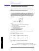
• With edge gating, the gate timing is controlled by user parameters
(gate delay and gate length) following the selected (rising or falling)
edge of the trigger signal. The gate passes a signal on the edge of the
trigger signal (after the gate delay time has been met) and blocks the
signal at the end of the gate length.
With edge gating, the gate control signal is usually an external
periodic TTL signal that rises and falls in synchronization with the
rise and fall of the pulsed radio signal. The gate delay is the time the
analyzer waits after the trigger event to enable the gate (see Figure
15-6).
• With level gating, the gate will pass a signal when the gate signal
meets the specified level (high or low). The gate blocks the signal
when the level conditions are no longer satisfied (level gating does
not use gate length or gate delay parameters).
Figure 15-6 Edge Trigger Timing Relationships
With Agilent PSA and ESA spectrum analyzers, there are three
different implementations for time gating; gated LO, gated video and
gated FFT. Gated LO and gated FFT are only available on the PSA
spectrum analyzers while gated video is only available on the ESA.