
User`s guide


60
Service
Maintenance
Maintenance
The only maintenance required for the 11970 Series Mixers is preventive maintenance. When you are
not using your mixer, cover its waveguide input with its waveguide cap. Also, though the 11970 Mixers
can absorb more punishment than is normal for such devices, you should avoid subjecting them to
unnecessary shock or vibration.
Repairs
The 11970 Mixers are NOT field-repairable. If your mixer fails, DO NOT try to repair it yourself, you
will void the warranty. Instead, notify the nearest Agilent office.
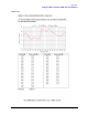
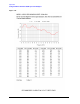
Replaceable Parts
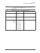
For a list of replaceable parts and accessories, see Table 3-1 on page 62.
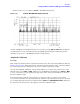
Circuit Description
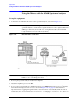
A schematic diagram of a 11970 Series Harmonic Mixer is shown in Figure 3-1 on page 61. The mixer
circuit employs two diodes arranged as an anti-parallel pair. These diodes are the termination for the
open end of the waveguide output. By employing a matched diode pair, even harmonic mixing is
enhanced while odd harmonic mixing is suppressed.
The waveguide input is exponentially tapered in both height and width. The height taper provides
impedance matching between the high impedance waveguide input and the low, dynamic impedance of
the diodes. The width taper creates a high-pass filter response which isolates the LO harmonics from the
standard-height waveguide. Without this isolation, the LO harmonics would reflect from the
standard-height waveguide back into the mixer and destructively interfere with the desired mixing
product.
LO harmonics are confined to the immediate vicinity of the diode pair by the low-pass filter, which has
as its first element a metal -insulator -semiconductor (MIS) capacitor. This improves the out-of-band
response. The internal diplexer separates the 3 - 6 GHz LO signal from the 321.4 MHz IF signal.