
User`s guide

37
Operation
Using the 11970A, Q, U, V, and W Mixers with the X- Series Signal Analyzers (Option EXM)
Loading the .csv file automatically populates the Description and Comment fields found under the
Corrections, Properties key. To edit these fields, press
Input/ Output, More, Corrections, Select
Correction
, select the correction number, press Properties, Description or Comment.
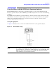
Compensating for IF cable and diplexer loss
The external diplexer has 1dB of loss at 300 MHz. The cable that connects the diplexer to the signal
analyzer has loss depending on cable length.
1. Press
Input/Output, External Mixer, Cable IF Loss and enter the cable loss plus the 1dB diplexer
loss.
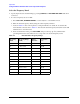
Manually entering conversion loss data
1. Locate the printed copy of the conversion loss data that has the text "For use with Agilent X-Series
analyzers only".
Or
Insert the CD provided with the mixer into a PC and navigate to the 70xxxxxx_X.pdf file. The file
contains tabular and graphic conversion loss data. Be careful to select the correct file since there are
three files provided for the 11970A, Q and V band mixers. Print the 70xxxxxx_X.pdf file to create a
printed copy.
NOTE For the 11970A, 11970Q and 11970V, this is the conversion loss file that is used
for almost all applications. however, for the mixer model numbers listed above,
there are two other 70xxxxxx_X.csv files on the CD that can be read and printed
using Windows notepad. See the notes under “Loading Conversion Loss Data for
the PXA Signal Analyzer” on page 35.
2. Press
Input/ Output, More, Corrections, Select Correction.
3. Choose a correction array from the list of Correction 1 through Correction 6. Correction 1 has a
provision to store antenna corrections, so if antenna corrections are required, reserve this array for
that use. If you want to see if anything is already stored in a particular correction, press
Correction,
Edit. To delete a correction table, press Return, assure the Select Correction key corresponds to the
correction you want to delete, and press
Delete Correction.
4. After selecting the correction number, press
Edit. Use the keys provided to enter the frequency and
amplitude (conversion loss) points from the calibration data table. Conversion loss values are entered
as positive numbers.When finished, press
Return.
5. It is possible to add a description and a comment of what the selected correction is, and have this
description appear on the Description or Comment key. Press
Properties, and connect a keyboard to
the instrument. For example, press
Comment and type 11970V Serial XXxxxxxxxx. Press Done.