
User`s guide

32
Operation
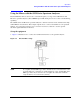
Using the Mixers with the E4440A, E4446A, or E4448A PSA Series Spectrum Analyzer (Option
AYZ)
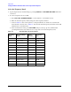
NOTE More correction points entered across the band in use will improve frequency
response accuracy. Up to 200 points may be defined for each set.
4. Once the desired correction points are entered, press
Return, Correction (On) to activate correction
set
Other. This will also turn corrections on resulting in a calibrated display. It is recommended that
the correction set entered be saved on the internal memory or the floppy drive for future reference.
See the PSA User’s and Programmer’s Reference guide for information on saving correction values.
Signal Identification
The IF output of a harmonic mixer will contain a signal at the intermediate frequency of the analyzer whenever the
harmonic frequency of the LO and the frequency of the RF differ by the intermediate frequency.
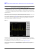
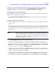
As a result, within a single harmonic band, a single input signal can produce multiple responses on the analyzer
display, only one of which is valid (see Figure 2-5). These responses come in pairs, where members of the valid
response pair are separated by 642.8 MHz and either the right-most (for negative harmonics) or left-most (for
positive harmonics) member of the pair is the correct response.
Figure 2-5
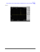
Identification of valid responses is achieved by simply turning on the signal-identification feature. (instrument
preset selects the Image Suppress signal identification mode.) Press
Input/Output, Input Mixer, Signal Ident (On)
and note that now only the valid response (35 GHz) remains.
Press
Peak Search to place a marker on the remaining response. Refer to Figure 2-6 on page 33.
After identifying a signal of interest, press
Signal Ident (Off) before making final amplitude measurements. Note
that Image Suppress should only be used to identify the fundamental signal and not for accurate amplitude
measurements.