
User`s guide


28
Operation
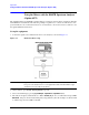
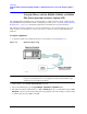
Using the Mixers with the E4407B Spectrum Analyzer (Option AYZ)
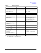
Manually Entering Conversion-Loss Data
1. The analyzer frequency band will be set to
26.5 – 40 GHz (A). To choose a different band, press Ext
Mix Band
and then press the desired band frequency range/letter key. For this example, we will use
band A, which ranges from 26.5 GHz to 40 GHz.
NOTE To correct for the conversion-loss of the harmonic mixer in use, the analyzer
amplitude correction feature is used.
2. Press
AMPLITUDE Y Scale, More, Corrections. Select a correction set for use with external mixing.
The recommended set to use is
Other although any available set could be used.
3. Press
Edit to enter the appropriate conversion loss data for the mixer in use. These values are listed
on the mixer, or a calibration sheet that is supplied with the mixer.
NOTE More correction points entered across the band in use will improve frequency
response accuracy. Up to 200 points may be defined for each set.
4. Once the desired correction points are entered, press
Return, Correction (On) to activate correction
set
Other. This will also turn corrections on resulting in a calibrated display. It is recommended that
the correction set entered be saved on the internal memory or the floppy drive for future reference.
See the ESA User’s and Programmer’s Reference guide for information on saving correction values.
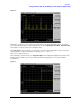
Signal Identification
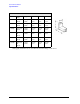
The IF output of a harmonic mixer will contain a signal at the intermediate frequency of the analyzer whenever the
harmonic frequency of the LO and the frequency of the RF differ by the intermediate frequency.
As a result, within a single harmonic band, a single input signal can produce multiple responses on the analyzer
display, only one of which is valid (see Figure 2-2 on page 29). These responses come in pairs, where members of
the valid response pair are separated by 642.8 MHz and either the right-most (for negative harmonics) or left-most
(for positive harmonics) member of the pair is the correct response.