
Technical data


Chapter 5 85
Spectrum Analyzer
Measuring Multiple Signals
Spectrum Analyzer
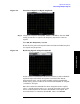
Resolving Small Signals Hidden by Large Signals
This procedure uses narrow resolution bandwidths to resolve two input
signals with a frequency separation of 50 kHz and an amplitude
difference of 60 dB.
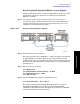
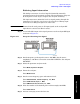
Step 1. Connect two sources to the analyzer input as shown in Figure 5-7.
Connect the output of signal generator #1 to port 2 of the directional
coupler and connect the output of signal generator #2 to port 3 (the
coupled port) of the directional coupler.
Figure 5-10 Setup for Obtaining Two Signals
Step 2. Set the signal sources as follows:
Set signal generator #1 to 300 MHz at –9 dBm. Set signal generator #2
to 300.450 MHz at –54 dBm. (These power levels plus the nominal
16 dB loss through the coupled arm and the nominal 1 dB loss through
the main arm of the directional coupler results in a signal 60 dB below
the first signal).
Step 3. Set the analyzer as follows:
Press
Mode Preset.
Press
FREQ Channel, Center Frequency, 300, MHz.
Press
SPAN X Scale, Span, 5, MHz.
Press
BW, 100, kHz.
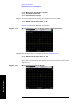
Step 4. Set the 300 MHz signal peak to the reference level:
Press
Peak Search, Mkr →, Mkr → Ref Lvl.
Note that the Agilent CSA 100 kHz filter shape factor of 8:1 has a
bandwidth of 840 kHz at the 60 dB point. The half-bandwidth
(420 kHz) is NOT narrower than the frequency separation of 450 kHz,
so the input signals can not be resolved.