
Technical data


Chapter 7 127
Stimulus Response Measurements (Option N8995A)
Distance to Fault
Stimulus Response Measurements
(Option N8995A)
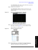
Press FREQ Channel, Units (Meters or Feet). Each time you press this
menu key, the selected option changes.
Step 7. Calibrate the measurement:
Press
FREQ Channel, Calibrate and follow the instructions on the
Calibration Wizard. The analyzer will calibrate over the desired
frequency range.
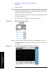
Figure 7-8 Distance to Fault Measurement, Calibrated
Step 8. Connect the test cable and calibration devices to the analyzer
RF Output, as shown in Figure 7-9, or in the calibration wizard.
This example uses an RG8A type cable.
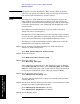
Figure 7-9 Distant to Fault Measurement
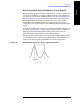
Step 9. The triangles (up to 4) will indicate the worst faults. Below the
graticule, the Return Loss, Distance, and VSWR of each fault is
indicated. (This cable has a fault indicated at 23 feet.)