
Technical data


Chapter 7 125
Stimulus Response Measurements (Option N8995A)
Distance to Fault
Stimulus Response Measurements
(Option N8995A)
Distance to Fault
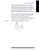
A signal is transmitted from the RF Output connector of the analyzer to
the cable-under-test. The signals reflected from faults in the cable are
received by the analyzer.
In performing this measurement, the analyzer uses frequency domain
reflectometry. The changing interference of the transmitted and
reflected signals contains information about the distance to one or more
faults. This information can be used to find the physical distance to the
faults. The distance displayed on the analyzer is the physical distance
to the probable faults, corrected for the cable loss and velocity factor of
the cable.
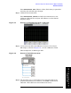
The analyzer provides two ways of measuring distance to fault:
• Manual Frequency Range. You select the start and stop
frequencies, which define the measured distance. Generally, the
typical start and stop frequencies you use will result in a measured
distance that will be larger than the distance over which you want to
look for faults. To help isolate faults over the length of interest, you
can set a displayed distance less than the measured distance. The
displayed distance is set using the
Start Distance and Stop Distance
menu keys on the [
Freq/Dist/Calibrate] menu. Keep in mind that there
are 256 measurement points across the measured distance.
Therefore, the measurement points across the chosen displayed
length will be a ratio of displayed distance to measured distance
times 256. The higher the ratio, the less measurement resolution. In
most cases, the resolution will be adequate to determine the faults,
but if more resolution is needed you can increase the span between
the start and stop frequencies (which will decrease the measured
distance) or use the other approach, automatic frequency range. If
the measurement distance is not long enough for the cable you are
testing, reduce the span between the start and stop frequencies
(which will increase the measurement distance) or use automatic
frequency range.
• Automatic Frequency Range. You select the measurement
distance, and the analyzer automatically selects the start and stop
frequencies. This measurement distance is set using the
Start
Distance
and Stop Distance menu keys on the [Freq/Dist/Calibrate]
menu. In this mode, the displayed and measured differences are the
same. There are 256 measurement points across the distance you
set. This approach provides the maximum measurement resolution
across the selected distance. The disadvantage is that the start and
stop frequencies are automatically set and may limit the analyzer's
ability to sweep through filters or lighting protectors. This mode is
best used for checking a cable that has no frequency limiting devices.