
Technical data


124 Chapter 7
Stimulus Response Measurements (Option N8995A)
Return Loss
Stimulus Response Measurements
(Option N8995A)
frequency range.
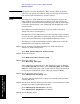
Step 6. Connect the test cable (if used) and calibration devices to the analyzer
RF Output, as shown in Figure 7-6, or in the calibration wizard. (If the
DUT is a two-port device, be sure to terminate the unused port in the
characteristic impedance of the device.)
Note that the units of the reference level are dB, indicating that this is
a relative measurement.
This example uses a 50 MHz low pass filter as the DUT.
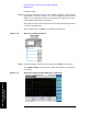
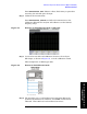
Figure 7-6 Return Loss Measurement
Step 7. Use the markers to measure the return loss and SWR at any point.
Press
Marker, Normal. Use the knob to place the marker at a frequency
of interest.
Figure 7-7 Return Loss Measurement Results, Calibrated.