
Technical data


Chapter 7 117
Stimulus Response Measurements (Option N8995A)
Two Port Insertion Loss
Stimulus Response Measurements
(Option N8995A)
Two Port Insertion Loss
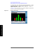
This procedure measures the loss or gain of a filter, amplifier, cable, or
other devices over a specified frequency range.
Insertion loss measurements are important in accurately quantifying
the amount of loss or gain a signal will incur as it passes through a
device. In S-parameter terms, insertion loss is referred to as an S
21
measurement. “S” stands for scattering.
NOTE Before you perform a two port insertion loss measurement, you must
first normalize the measured values for insertion loss by compensating
for the loss associated with the devices (adapters, cables) that connect
the analyzer to the device or assembly being tested. Otherwise, the loss
introduced by these connecting devices is added to the loss of the device
under test.
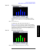
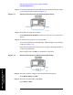
Step 1. To measure the rejection of a low pass filter, connect the RF Output of
the analyzer to the RF Input as shown in Figure 7-2.
NOTE DO NOT make the connection at this time. You will be directed when to
make the connections later in the procedure.
This example uses a 50 MHz low pass filter as the DUT.
Step 2. Set the analyzer to the Two Port Insertion Loss measurement:
Press
Mode, Stimulus/Response, Two Port Insertion Loss
Step 3.
Preset the analyzer:
Press
Mode Preset.
Step 4. Set the start and stop frequencies:
Press
FREQ Channel, Start Freq, 10, MHz.
Press
FREQ Channel, Stop Freq, 250, MHz.
Step 5. Turn averaging off:
Press
Meas Setup, Avg Mode, Off.
Step 6. Set the tracking generator output power to –15 dBm:
Press
Source, Source Level (Manual), –15, dBm.
CAUTION Excessive signal input may damage the DUT. Do not exceed the
maximum power that the device under test can tolerate.