
Technical data


102 Chapter 5
Spectrum Analyzer
Using the Analyzer as a Fixed Tune Receiver
Spectrum Analyzer
Using the Analyzer as a Fixed Tune Receiver
This section provides information on using the analyzer as an AM
receiver to measure modulation parameters.
This section includes the following measurement:
“Measuring the Modulation Rate of an AM Signal” on page 102
CAUTION Ensure that the total power of all signals at the analyzer input does not
exceed +33 dBm (2 watts).
Basic Assumption
The material in this section is presented with the assumption that you
understand the front and rear panel layout, and display annotations of
your analyzer. If you do not, refer to the Measurement Guide “Front and
Rear Panel Features”.
Measuring the Modulation Rate of an AM Signal
This section demonstrates how to determine parameters of an AM
signal, such as modulation rate and modulation index (depth) by using
frequency and time domain measurements (refer to the concepts
chapter in the Measurement Guide for “AM and FM Demodulation
Concepts” on page 133 for more information).
To obtain an AM signal, you can either connect a source transmitting an
AM signal, or connect an antenna to the analyzer input and tune to a
commercial AM broadcast station. For this demonstration an RF source
is used to emulate an AM signal.
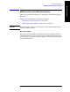
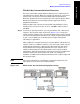
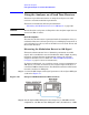
Step 1. Connect the RF Output of the signal generator to the analyzer RF Input
as shown in Figure 5-7.
Figure 5-25 Setup for AM Demodulation Measurement
Step 2. Set the Agilent ESG RF signal source frequency to 300 MHz and the
amplitude to
−10 dBm. Set the AM depth to 80%, the AM rate to 1 kHz