Agilent 1100 Series Valves User’s Guide Agilent Technologies
Notices © Agilent Technologies, Inc. 2002, 2004 Warranty No part of this manual may be reproduced in any form or by any means (including electronic storage and retrieval or translation into a foreign language) without prior agreement and written consent from Agilent Technologies, Inc. as governed by United States and international copyright laws. The material contained in this document is provided “as is,” and is subject to being changed, without notice, in future editions.
In This Guide… The Agilent 1100 Series valves provide the user a comprehensive solutions for more flexibility through solvent selection and column selection. They offer new automation capabilities for sample preparation as well as higher sample throughput with alternating column regeneration. The Agilent 1100 Series valves are fully integrated in the CAN environment (control area network) of the Agilent 1100 HPLC system and can be controlled by the Agilent ChemStation Software.
Chapter 3, “Maintenance, Repair, and Troubleshooting,” starting on page 19 will describe recommended maintenance and repair procedures as well as troubleshooting tools. Chapter 4, “Valve Applications,” starting on page 33 will describe common application, e.g. alternating column regeneration, and how to setup your valves for these applications.
contents Contents 1 Installation and Configuration Site Requirements 2 Unpacking the 1100 Series Valve Damaged Packaging 3 Delivery Checklist 3 3 Hardware Installation 5 Setting up the CAN connection 6 Setting up the power connection to other Agilent 1100 Series Modules 7 Setting up the power connection to the external power supply 7 Software Configuration 2 8 Operation Operating the Valve using Agilent ChemStation Handheld Controller functions 3 12 16 Maintenance, Repair, and Troubleshooting St
contents 4 Valve Applications Alternating Column Regeneration 34 Sample enrichment and Sample stripping Sample enrichment 38 Sample stripping 39 5 Column Selection 42 Solvent Selection 44 38 Parts General Parts 48 Capillaries and Fittings for analytical and preparative flow rates 50 Capillaries and Fittings for micro valves 51 6 Specifications 7 Safety Information General Safety Information 60 Lithium Batteries Information Radio Interference Sound Emission 64 65 Solvent Information 66 A
Agilent 1100 Agilent 1100 Series Valves User’s Guide 1 Installation and Configuration Site Requirements 2 Unpacking the 1100 Series Valve 3 Hardware Installation 5 Software Configuration 8 Agilent Technologies 1
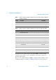
1 Installation and Configuration Site Requirements Site Requirements The requirements for the Agilent 1100 Series Valves are displayed Table 1 and Table 2 on page 2. The 24 Volts DC power can be supplied by an external power supply (0950-4422) or by one of the following Agilent 1100 Series modules with DC CAN adapter.
Installation and Configuration 1 Unpacking the 1100 Series Valve Unpacking the 1100 Series Valve Damaged Packaging If the delivery packaging shows signs of external damage, please call your Agilent Technologies sales and service office immediately. Inform your service representative that the 1100 Series Valve may have been damaged during shipment. CAUTION If there are signs of damage, please do not attempt to install the valve.
1 Installation and Configuration Unpacking the 1100 Series Valve Table 3 Delivery checklist for Agilent 1100 Series valves G1157A, G1158A, G1159A and G1160A (continued) Quantity Description 1 • Hex Key 3/32” 1 • wrench 8710-0510 1 • socket wrench (Rheotool) 1/4 8710-2391 Table 4 Part Number Delivery checklist for Agilent 1100 Series micro valves G1162A and G1163A Quantity Description Part Number 1 1100 Series Micro Valve 1 Declaration of conformity 1 Rail assembly for Column Organiz
Installation and Configuration 1 Hardware Installation Hardware Installation The Agilent 1100 Series External Valves can be installed in two different ways. They can either be placed on free bench space near the Agilent 1100 Series HPLC system or they can be mounted on the Agilent G1383A Column Organizer as displayed in Figure 1. The column organizer should be located on the right side of the 1100 Series stack, which includes the autosampler.
1 Installation and Configuration Hardware Installation In order to install a valve on the G1383A Column Organizer the Organizer Rail Assembly must be installed on the two mounting poles using the clips from the Organizer Rail Assembly. All External Valves have a bracket on the side which slides over the metal part of the Organizer Rail Assembly. Two CAN connectors and one DC-CAN connector are located at the back panel of the 1100 Series Valve Assemblies as displayed in Figure 2.
Installation and Configuration 1 Hardware Installation Setting up the power connection to other Agilent 1100 Series Modules The power for the Agilent 1100 Series External Valves can be supplied by one of the following 1100 Series modules: • Agilent 1100 Series Preparative Pump (G1361A) • Agilent 1100 Series Fraction Collector (G1364A, G1364B, G1364C, G1364D) • Agilent 1100 Series Well-Plate Autosampler (G1367A) • Agilent 1100 Series Micro Well-Plate Autosampler (G1377A) • Agilent 1100 Series Dual Loop Au
1 Installation and Configuration Software Configuration Software Configuration The 1100 Series Valves can be controlled by the Agilent ChemStation Rev. A.09.03 or higher. CAUTION The maximum number of all modules (including CAN-slave valves) in your Agilent 1100 Series LC system must not exceed 13. Contact your local sales and service representative to verify, if your configuration is supported. This is especially important, if the number of module is close to 13.
Installation and Configuration 1 Software Configuration Figure 3 Agilent 1100 Series Valves Valve configuration 9
1 Installation and Configuration Software Configuration 10 Agilent 1100 Series Valves
Agilent 1100 Agilent 1100 Series Valves User’s Guide 2 Operation Operating the Valve using Agilent ChemStation 12 Handheld Controller functions 16 Agilent Technologies 11
2 Operation Operating the Valve using Agilent ChemStation Operating the Valve using Agilent ChemStation After the Agilent 1100 Series Valves have been installed and configured, the valve parameters can be edited in the Agilent ChemStation. Choose Setup Valve from the Instrument menu to open the valve dialog box as displayed in Figure 4. Figure 4 NOTE Valve Setup dialog box The example displays the valve setup for the 2 position/10 port valve (G1157A). The interface for the other valves are similar.
Operation 2 Operating the Valve using Agilent ChemStation After the run is finished, the valve always switches to the starting position. If “Use current” is selected, the valve remains in the current position after the run. This behavior is exhibited in Figure 5 on page 13. Restore Starting Position Starting Position NOT restored Figure 5 Valve Control Valve Name Define the Valve Name that is used for the method report and the Instrument actuals. The Valve Name is limited to 20 characters.
2 Operation Operating the Valve using Agilent ChemStation Position Descriptions Define the Position Description that is used for the method report and the instrument actuals. The Position Description is limited to 19 characters.
Operation 2 Operating the Valve using Agilent ChemStation Next position after run If Next position after run is checked, the valve will switch to the next available position after the run is completed and remains there for the next run. For this selection the Position field is greyed out (see Figure 5 on page 13).
2 Operation Handheld Controller functions Handheld Controller functions With firmware revision B.03.11 or higher the following valve functions with the Agilent 1100 Series handheld controller G1323B are available. Complete control of an 1100 Series Valve during an LC analysis requires ChemStation Revision A.09.03 or higher.
Operation 2 Handheld Controller functions Figure 8 Valve Synchronization Setting the EMF limit and switch counter 1 From the startup screen of the Agilent 1100 Series Handheld Control Module select System (F5) 2 Select Records (F4) and scroll through the displayed module list and select the Agilent 1100 Series Valve. 3 Press EMF (F1) and then select 1 Setup Limits. 4 In the upcoming dialog (Figure 9) edit the EMF limit.
2 Operation Handheld Controller functions 18 Agilent 1100 Series Valves
Agilent 1100 Agilent 1100 Series Valves User’s Guide 3 Maintenance, Repair, and Troubleshooting Status Indicators 20 Maintenance and Repair 21 System Errors and Troubleshooting 29 Agilent Technologies 19
3 Maintenance, Repair, and Troubleshooting Status Indicators Status Indicators The instrument status indicator indicates one of four possible instrument conditions: • When the status indicator is OFF, the instrument is in a prerun condition, and is ready to begin an analysis. • A green status indicator indicates the instrument is performing an analysis (run mode). • A yellow status indicator indicates a not-ready condition.
Maintenance, Repair, and Troubleshooting 3 Maintenance and Repair Maintenance and Repair The maintenance of the Agilent 1100 Series valves (G1157A, G1158A, G1159A, G1160A) includes the exchange of the stator face and the rotor seal. In addition it might be necessary to exchange the stator head, if the threads are worn out or if a fitting is broken and cannot be removed from the stator head.
3 Maintenance, Repair, and Troubleshooting Maintenance and Repair Replacing the stator face and the rotor seal for standard valves (G1157A, G1158A, G1159A, G1160A) Disassembling the valve head 1 Use the Hex Key to remove the Stator Screws (1) from the Stator Head (2). 2 Disassemble the Stator Head and Stator Face (5) from the Stator Ring (4). The Stator Face usually remains on the Stator Head. 3 Remove the three Stator Ring Screws (3) and take off the Stator Ring (4).
Maintenance, Repair, and Troubleshooting 3 Maintenance and Repair 7 9 8 6 Figure 11 Valve body (7) and Rotor seal (6) 2 Align the Stator Ring (4) that the two short pins on the ring enter the matching holes in the body (7). 3 Insert the three Stator Ring Screws (3). Turn each of the screws an equal amount until the they are finger-tight, then tighten them another half turn. 4 Mount the new Stator Face (5) onto the Stator Head (2).
3 Maintenance, Repair, and Troubleshooting Maintenance and Repair Replacing the rotor seal for micro valves (G1162A and G1163A) Disassembling the valve head 1 Use the Hex Key to remove the Stator Screws (1) from the Stator Head (2). 2 Disassemble the Stator Head (2) 3 Remove the three Stator Ring Screws (3) and take off the Stator Ring (4). 4 Remove the Rotor Seal (5) from the Valve Body (6). The Rotor Seal is mounted on three pins.
Maintenance, Repair, and Troubleshooting 3 Maintenance and Repair Reassembling the valve head 1 Mount the new Rotor Seal (5) with the grooves facing the Stator Head (2). The three pins on the Shaft Assembly fit into the matching holes in the Rotor Seal only one way. 2 Mount the Stator Ring on the Shaft Assembly that the two pins fit to the matching holes on the Valve body. 3 Assemble the Stator Head (2) that the pin in the Stator Ring fits to the matching hole in the Stator Head.
3 Maintenance, Repair, and Troubleshooting Maintenance and Repair Table 6 Rebuild kits and repair parts for Agilent 1100 Series Vales (continued) Description • Stator heads 26 part number Stator head for G1157 (2 position/10 port valve 0101-1362 Stator head for G1158 (2 position/6 port valve) 0100-1850 Stator head for G1159 (6 position selection valve) 0101-1364 Stator head for G1160 (12 position/13 port valve) 0101-1365 Stator head for G1162A (2 position/6 port micro valve) 0100-2089 Stator
Maintenance, Repair, and Troubleshooting 3 Maintenance and Repair Early Maintenance Feedback (EMF) Depending on the application the valve will perform many thousands of actuations without any visible signs of wear. In order to minimize downtime the Agilent ChemStation offers Early Maintenance Feedback (EMF) for the 1100 Series Valves. EMF monitors the number of switches of the 1100 Series valves, and provides feedback when a user-settable limit is exceeded.
3 Maintenance, Repair, and Troubleshooting Maintenance and Repair Resetting the EMF counter 1 Switch to the Diagnostics View of the ChemStation. 2 Select Valve from the Maintenance menu. 3 In the upcoming dialog box click on Reset Counter (see also Figure 18 on page 32). The procedure to reset the EMF counter with the 1100 Series handheld controller is described on page 17.
Maintenance, Repair, and Troubleshooting 3 System Errors and Troubleshooting System Errors and Troubleshooting System Errors No line power Figure 14 Display of instrument actuals at a no line power state Error Cause If the 24 volt DC line power is not available, the yellow Notready status is displayed in the instrument actuals. If you try to switch the valve, this status changes to Power.
3 Maintenance, Repair, and Troubleshooting System Errors and Troubleshooting CAN failure Figure 15 CAN failure Error Cause If the red Pow. fail status is visible the CAN communication is interrupted. Actions 1 Check the CAN connection at the valve and at all other modules. 2 Check that the maximum number of 13 Agilent 1100 Series modules (including CAN slaves) is not exceeded. 3 Restart the ChemStation.
Maintenance, Repair, and Troubleshooting 3 System Errors and Troubleshooting Unknown Position Figure 17 Error Cause Unknown Position An unknown position is indicated Act. Pos.: 0=- Actions 1 Synchronize the valve as described on page 32. 2 Restart the ChemStation. 3 Disconnect and replug the CAN cable.
3 Maintenance, Repair, and Troubleshooting System Errors and Troubleshooting Valve Synchronization If the valve failed to switch or if the current position of the valve is unknown, it might be necessary to synchronize the valve. To synchronize the valve Note Step 1 Switch to the Diagnostics view. 2 Select Valve from the Maintenance menu. The valve should now display the Current Position as displayed in Figure 18.
Agilent 1100 Agilent 1100 Series Valves User’s Guide 4 Valve Applications Alternating Column Regeneration 34 Sample enrichment and Sample stripping 38 Column Selection 42 Solvent Selection 44 In this chapter selected applications for the Agilent 1100 Series Valves will be described.
4 Valve Applications Alternating Column Regeneration Alternating Column Regeneration Alternating column regeneration is a convenient way to increase the sample throughput. The Agilent 1100 Series 2 position/ 10 port valve (G1157A) can be used in combination with the Agilent LC and LC/MS modules to increase the efficiency in laboratories running large amounts of samples.
Valve Applications 4 Alternating Column Regeneration If the valve is switched to position 1 the eluent pump delivers the mobile phase through the injection loop of the autosampler into port 2 of the 1100 Series Valve. The sample is separated on column 1 and analyzed by the detector. Simultaneously a second regeneration pump flushes and equilibrates column 2. After the analysis of the sample is finished on column 1, column 2 is prepared for an immediate injection.
4 Valve Applications Alternating Column Regeneration Capillary Kit (G1156-68711) for alternating column regeneration with G1157A (analytical scale) Table 7 From To ID/mm Length/mm part number Injector/Autosampler Valve (port 2) 0.17 500 G1328-87600 Valve (port 3) Column 1 0.17 600 5021-1819 Column 1 Valve (port 6) 0.17 400 5065-9933 Valve (port 7) Detector 0.17 600 5065-9933 Valve (port 8) Column 2 0.17 400 5021-1819 Column 2 Valve (port 1) 0.
Valve Applications 4 Alternating Column Regeneration Capillary Kit (G1156-68713) for alternating column regeneration with G1157A (preparative scale) Table 9 Capillaries From To ID/mm Length/mm part number Injector/Autosampler Valve (port 2) 0.5 600 G2260-87300 Valve (port 3) Column 1 0.5 600 G2260-87301 Column 1 Valve (port 6) 0.5 400 G2260-87300 Valve (port 7) Detector 0.5 600 G2260-87300 Valve (port 8) Column 2 0.5 400 G2260-87301 Column 2 Valve (port 1) 0.
4 Valve Applications Sample enrichment and Sample stripping Sample enrichment and Sample stripping Sample enrichment and sample stripping methods can be used to separate samples from complex matrices, such as biological fluids, food extracts or wastewater. This might be necessary to avoid interference of the matrix during separation and detection or even damage of the column. You can use the 1100 Series 2 position/ 6 port valve (G1158A) to automate these techniques for LC and LC/MS analysis.
Valve Applications 4 Sample enrichment and Sample stripping For the sample enrichment phase the valve is switched to position 1. The eluent Pump A transfers the injected sample onto the enrichment column. The sample is retained and enriched on this column, whereas the sample matrix is flushed into the waste. At the same time the second eluent pump B is equilibrating the analytical column.
4 Valve Applications Sample enrichment and Sample stripping Figure 22 on page 39 illustrates how the Agilent 1100 Series 2 position/ 6 port valve can be used for sample stripping. In valve position 1 Pump A transfers the complete sample matrix onto the pre-column 1, where the matrix is trapped while the analytes are eluted and flushed to column 2 for analysis. Then the valve switches to position 2.
Valve Applications 4 Sample enrichment and Sample stripping Table 12 Fittings, screws, and ferrules Description Qty part number 1/16” fittings and ferrules 10/pk 1 5062-2418 fingertight fitting (long) 1 5062-8541 (10/pk) fitting screw (long) 5 5065-4454 (10/pk) front ferrule 10/pk 1 5180-4108 back ferrule 10/pk 1 5180-4114 ZDV fitting 1 0100-0900 0.18 ID PEEK tubing (1.
4 Valve Applications Column Selection Column Selection With the Agilent 1100 Series 6 position selection valve (G1159A) and the capillary kit for Column Selection (Table 13 and Table 14 on page 43) you can set up your Agilent 1100 Series LC or LC/MS system for use with up to 6 columns as displayed in Figure 23. Or you can use the system with 5 columns and one flow path for flow injection analysis or for flushing the system.
Valve Applications 4 Column Selection Capillary Kit (G1156-68712) for column selection with G1159A (analytical scale) Table 13 Capillaries From To Injector/Autosampler ID/mm Length/mm part number Valve (IN) 1 0.17 500 G1328-87600 Valve (X) Column X 6 0.17 400 5021-1819 Column X Valve (X’) 6 0.17 400 5021-1819 Valve (OUT) Detector 1 0.17 600 G1328-87600 Table 14 Qty.
4 Valve Applications Solvent Selection Solvent Selection The 1100 Series 12 position / 13 port valve can be used for solvent selection (flow rate < 10 ml/min) as illustrated in Figure 24. It offers automated access to 12 different eluents.
Valve Applications 4 Solvent Selection Tubing Kit (G1160-68706) for solvent selection (4 solvents) with G1160A, degasser and isocratic pump (flow rate < 10 ml/min) Table 15 Tubing From To Qty. ID/mm Length/mm part number Solvent Bottle Degasser 4 1.5 1000 G1311-60003 Degasser Valve (pos.1-12) 4 1.5 600 G1160-67300 Valve (OUT) Pump Inlet 1 1.5 600 G1160-67300 Table 16 Finger-tight fittings Description Qty part number Adapter, PEEK int. 1/4-28 to ext.
4 Valve Applications Solvent Selection 46 Agilent 1100 Series Valves
Agilent 1100 Agilent 1100 Series Valves User’s Guide 5 Parts General Parts 48 Capillaries and Fittings for analytical and preparative flow rates 50 Capillaries and Fittings for micro valves 51 In this chapter you will find part numbers and part descriptions for maintenance and repair.
5 Parts General Parts Table 17 Description part number • CAN cable, 1m long 5181-1519 • DC-Can cable 5181-1533 • External Power Supply 0950-4422 • Rail assembly for Column Organizer 5065-4450 Table 18 48 General parts Exchange valve assemblies Description part number • 2 position/10 port valve G1157-60001 • 2 position/6 port valve G1158-60001 • 6 position selction valve G1159-60001 • 12 position/13 port selection valve G1160-60001 • 2 position/6 port micro valve G1162-60001 • 2 p
Parts Table 19 Rebuild kits and repair parts for Agilent 1100 Series Valves Description • Rebuilt kits and rotor seals • Stator heads Agilent 1100 Series Valves 5 part number Rebuild kit for G1157A (2 position/10 port valve) 0101-1359 Rebuild kit for G1158A (2 position/6 port valve) 0101-1358 Rebuild kit for G1159A (6 position selection valve) 0101-1290 Rebuild kit for G1160A (12 position/13 port valve) 0101-1288 Rotor seals for G1158A (2 position/6 port valve) 0100-1855 (Vespel) 0100-1854 (
5 Parts Capillaries and Fittings for analytical and preparative flow rates Table 20 Table 21 Capillary and tubing kits Description part number • Capillary kit: alternating column regeneration (analytical) for valve G1157A (for details see Table 7 and Table 8 on page 36) G1156-68711 • Capillary kit alternating column regeneration (preparative) for valve G1157A (for details see Table 9 and Table 10 on page 37) G1156-68713 • Capillary kit: alternating Sample enrichment/stripping (analytical) for val
Parts 5 Capillaries and Fittings for micro valves For the operation of the Agilent 1100 Series Micro Valves we recommend the following fittings and PEEK coated fused silica capillaries as listed in Table 22, Table 23 and Table 24.
5 Parts Table 23 Fitting Types Fittings and ferrules Fitting type A B C D Table 24 52 PEEK coated fused silica capillaries for micro valves i.D./µm Length/mm Volume/µl Fitting type* Part number 100 150 1.178 B/C G1375-87317 100 200 1.570 B/C G1375-87312 100 220 1.728 B/B G1375-87305 100 550 4.320 B/C G1375-87306 100 1100 8.639 B/D G1375-87315 100 1100 8.639 B/B G1375-87303 75 400 1.767 D/E G1375-87308 75 500 3.209 C/D G1375-87311 75 700 3.
Parts Table 24 5 PEEK coated fused silica capillaries for micro valves (continued) i.D./µm Length/mm Volume/µl Fitting type* Part number 50 220 0.432 B/B G1375-87301 50 280 0.550 C/D G1375-87309 50 400 0.785 E/D G1315-68703 50 500 0.982 C/D G1375-87304 50 550 1.080 B/C G1375-87310 25 100 0.049 C/D G1375-87320 25 220 0.108 D/D G1375-87321 25 350 0.172 C/D G1375-87322 25 550 0.270 C/D G1375-87323 25 700 0.
5 54 Parts Agilent 1100 Series Valves
Agilent 1100 Agilent 1100 Series Valves User’s Guide 6 Specifications G1157A Agilent 1100 Series 2 position / 10 port valve 56 G1158A Agilent 1100 Series 2 position / 6 port valve 56 G1159A Agilent 1100 Series 6 position selection valve 56 G1160A Agilent 1100 Series 12 position/ 13 port selection valve 57 G1162A 1100 Series 2 position/ 6 port micro valve 57 G1163A 1100 Series 2 position/ 10 port micro valve 57 In this chapter you will find the specifications of the 1100 Series valves.
6 Specifications Table 25 Liquid contacts: Stainless Steel and PEEK Port size: Accepts 10-32 male threaded fittings Flow passage diameters: Stator and stator face assembly 0.6-mm (0.024”), rotor seal 0.6-mm (0.024”) Volume in flow passage: Stator (includes stator face seal) 2.1 µl/hole, rotor seal 0.7 µl/groove Maximum pressure: 41 MPa (408 bar, 6000 psi) Recommended flow range: 0.
Specifications 6 * The G1159A 1100 Series 6 positions selection valve can be used at flow rates up to 100 ml/min, but without valve switching. In most cases e.g. column selection the valve switches during the postrun or prerun, when the flow can be reduced. Table 28 G1160A Agilent 1100 Series 12 position/ 13 port selection valve Liquid contacts: Stainless steel and PEEK Port size: Accepts 10-32 male threaded fittings Flow passage diameters: 1.0-mm (0.
6 Specifications Table 30 58 G1163A 1100 Series 2 position/ 10 port micro valve (continued) Volume in flow passages: Stator (20° ports)27.2 nl, (45° ports) 30.5 nl, rotor seal 25.0 nl/groove Maximum pressure: 41 MPa (408 bar, 6000 psi) Recommended flow range: 0.
Agilent 1100 Agilent 1100 Series Valves User’s Guide 7 Safety Information General Safety Information 60 Lithium Batteries Information 63 Radio Interference 64 Sound Emission 65 Solvent Information 66 Agilent Technologies on Internet 67S Agilent Technologies 59
7 Safety Information General Safety Information General Safety Information The following general safety precautions must be observed during all phases of operation, service, and repair of this instrument. Failure to comply with these precautions or with specific warnings elsewhere in this manual violates safety standards of design, manufacture, and intended use of the instrument. Aligent Technologies assumes no liability for the customer’s failure to comply with these requirements.
Safety Information General Safety Information 7 attempt internal service or adjustment unless another person, capable of rendering first aid and resuscitation, is present. Do not replace components with power cable connected. Do not operate the instrument in the presence of flammable gases or fumes. Operation of any electrical instrument in such an environment constitutes a definite safety hazard. Do not install substitute parts or make any unauthorized modification to the instrument.
7 Safety Information General Safety Information Safety Symbols Table 31 shows safety symbols used on the instrument and in the manuals. Table 31 Symbol ! Safety Symbols Description The apparatus is marked with this symbol when the user should refer to the instruction manual in order to protect the apparatus against damage. Indicates dangerous voltages. Indicates a protected ground terminal.
Safety Information Lithium Batteries Information 7 Lithium Batteries Information WA R N I N G Danger of explosion if battery is incorrectly replaced. Replace only with the same or equivalent type recommended by the equipment manufacturer. Lithium batteries may not be disposed-off into the domestic waste. Transportation of discharged Lithium batteries through carriers regulated by IATA/ICAO, ADR, RID, IMDG is not allowed.
7 Safety Information Radio Interference Radio Interference Never use cables other than the ones supplied by Aligent Technologies to ensure proper functionality and compliance with safety or EMC regulations. Test and Measurement If test and measurement equipment is operated with equipment unscreened cables and/or used for measurements on open set-ups, the user has to assure that under operating conditions the radio interference limits are still met within the premises.
Safety Information Sound Emission 7 Sound Emission Manufacturer’s Declaration This statement is provided to comply with the requirements of the German Sound Emission Directive of 18 January 1991. This product has a sound pressure emission (at the operator position) < 70 dB.
7 Safety Information Solvent Information Solvent Information Observe the following recommendations on the use of solvents. Solvents Brown glass ware can avoid growth of algae. Always filter solvents, small particles can permanently block the capillaries. Avoid the use of the following steel-corrosive solvents: • Solutions of alkali halides and their respective acids (for example, lithium iodide, potassium chloride, and so on).
Safety Information Agilent Technologies on Internet 7 Agilent Technologies on Internet For the latest information on products and services visit our worldwide web site on the Internet at: http://www.agilent.com Select “Products” - “Chemical Analysis” It will provide also the latest firmware of the Agilent 1100 series modules for download.
7 68 Safety Information Agilent Technologies on Internet Agilent 1100 Series Valves
Index A accessory kit, 3 Agilent ChemStation, 8, 12 Agilent on internet, 67 alternating column regeneration, 34 analytical scale, 36 preparative scale, 37 analytical scale alternating column regeneration, 36 column selection, 43 sample enrichment, 40 EMF counter, 28 EMF info pad, 27 EMF limit, 17, 27 F ferrules, 52 finger-tight fittings, 45 fittings, 45, 52 flow injection analysis, 42 flow range, 56, 58 flushing, 42 B G battery safety information, 63 gradient elution, 34 C CAN connection, 6 CAN failu
Index stator ring, 22, 24 Status Indicators, 20 switch failure, 30 switching the valve, 16 synchronization, 16, 32 system errors, 29 T time table, 14 troubleshooting, 29 tubing kit, 45, 50 U unknown position, 31 use current, 12 uv-radiation, 66 V valve assemblies, 48 valve configuration, 9 valve head, 22, 24 valve name, 13 valve parameters, 12 valve synchronization, 32 70 Agilent 1100 Series Valves
www.agilent.