
User Manual Part 2


112
2852 A EN 20070205
DRYSTAR AXYS
Establishing the image geometry reference values
for mammography application (DT 2 Mammo)
(optional)
Procedure
1 Print the QC mammography test image or use the previously printed test image.
For an example, see “QC test image for mammography applications (DT 2 Mammo)
(optional)” on page 107.
2 To determine the reference values for geometry, measure the distances A and B
of the geometric square on the test image.
3 Record these values as reference dimensions Aref and Bref on Chart 4
(‘Drystar AXYS Geometric Consistency Control Chart’). Refer to “Charts for
mammography QC (optional)” on page 155.
These charts will be used for the annual quality test. For more information, refer to
“Performing the Annual QC tests for mammography application (DT 2 Mammo)
(optional)” on page 120.
4 Save this film for future reference.
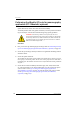
WARNING: Make sure to measure distance A from the left edge of
the left line to the right edge of the right line and distance B from
the upper edge of the upper line to the lower edge of the lower
line.
WARNING: We strongly recommend using a 30 cm (12-inch)
machinist scale with 0.5 mm divisions (1/64 inch).