
User Manual

,
© AGD Systems Ltd 2010. All rights reserved., the information contained in this document is the property of AGD Systems Ltd., and is supplied
without liability for errors or omissions. AGD315 User Manual Page 8 of 12
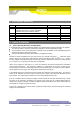
6 MESSAGE FORMATS
6.1 Standard Messages
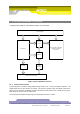
In normal operation, the radar produces a single standard message of the following form
<frame number>,<radar mode>,<detection direction>,
<cosine correction>:<debug info>#<target information><CR>
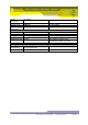
A sample message sequence from a typical roadside test is shown below:
0001917903,R,A,22: #T0:A,29,11,11.7,70.3
0001917904,R,A,22: #T0:A,29,11,11.7,60.4
0001917905,R,A,22: #T0:A,29,11,11.7,65.5
0001917906,R,A,22: #T0:A,29,12,12.8,61.0
0001917907,R,A,22: #T0:A,29,12,12.8,66.1
0001917908,R,A,22: #T0:A,28,12,12.8,68.4
0001917909,R,A,22: #T0:A,28,13,13.8,65.5
0001917910,R,A,22: #T0:A,28,12,12.8,67.3
0001917911,R,A,22: #T0:A,27,13,13.8,63.0
0001917912,R,A,22: #T0:A,28,13,13.8,71.2
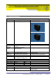
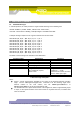
The fields in each message are described in the table below:
Field Descriptor
Explanation
Comments
Frame number
Increments every frame
Reset if detector is rebooted
Radar Mode
R – ranging mode
Factory set by AGD
Detection direction
Advance, Recede, Bidirectional
See section 8 – radar usage
Cosine correction
Mounting angle to the road
Debug into
Between : and !
AGD use only
Target Information
Target number, Direction, Range
bin, Doppler Bin, Speed,
Power Level
Range bin = 2 metres
Doppler bin = ~1 mph
Speed includes cosine correction
and is in either mph or kph
Table 2 Message Descriptors
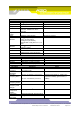
Notes:
Speed – vehicle speed will be modified by the cosine of the dominant detector mounting
angle. Use the *AD<space><angle><cr> command to set the mounting angle of the
detector relative to the road surface, and use UNITS<space>MPH<cr> or
UNITS<space>KPH<cr> to set the measurement units.
The fundamental unit of speed measurement is the Doppler bin, which is approximately equal
to 1mph, so the speed resolution of the radar cannot be any better than this, no matter what
units are selected.