
User Manual

,
© AGD Systems Ltd 2010. All rights reserved., the information contained in this document is the property of AGD Systems Ltd., and is supplied
without liability for errors or omissions. AGD315 User Manual Page 7 of 12
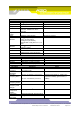
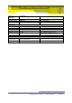
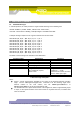
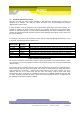
Parameter
Value
Baud rate
115200
Data bits
8
Parity bits
None
Stop bits
1
Flow control
None
Table 1 Default UART Settings
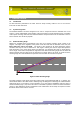
The RS422 provides the primary output of the radar in the form of ASCII messages. These messages
provide speed and range information.
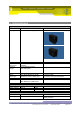
5.1.2 LED’s
No LED’s are visible from the outside of the unit. A number of internal LED’s are provided for test and
debug purposes.
5.1.3 Temperature Sensor
A digital temperature sensor has been installed on the digitiser board. This allows the processor to
monitor environmental conditions. The temperature of the radar may be requested using the TEMP
command.
5.1.4 Non Volatile Memory
An EEPROM is installed on the board to provide non volatile memory. The primary use of this
EEPROM is to store configuration and calibration data.
5.2 Power supply board CB-180
The radar is powered using a DC voltage in the range of 9 to 30 volts. The radar is polarity protected
using a diode. The radar can take a very large current doing power up that is of the order of amps.
However, this current only lasts for ~1ms and should not affect most applications.
5.2.1 Input Protection
A one shot anti-surge (T) fuse with a 630mA rating has been installed to protect against electrical
short circuit fault conditions.