
User Manual

,
© AGD Systems Ltd 2010. All rights reserved., the information contained in this document is the property of AGD Systems Ltd., and is supplied
without liability for errors or omissions. AGD315 User Manual Page 6 of 12
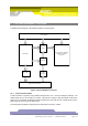
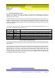
5 SYSTEM HARDWARE OVERVIEW
A simplified block diagram of the AGD315-205/207 is shown below:
4k x 18 bit
FIFOS
12 bit ADC
Radar Transceiver Module
DDS \ DAC
Amplifier
& Filter
Subsystem
PIC 18F452
TI C6711 DSP & associated
components (SDRAM,
FLASH etc)
Power Supplies
Figure 1 System Hardware Overview
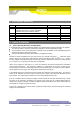
5.1.1 Serial interface, RS422
A UART interface is provided using RS422 voltage levels, over a 4 wire (full duplex) interface. The
default baud rate for this interface is 115200. This may be changed using the BAUD command to
speeds of up to 921600. The BAUD command will store the baud rate into non volatile memory of the
radar ready for the next time the radar boots.
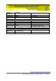
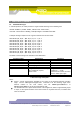
The serial interface default setup during normal operation is shown in Table 1.