
User Manual

,
© AGD Systems Ltd 2010. All rights reserved., the information contained in this document is the property of AGD Systems Ltd., and is supplied
without liability for errors or omissions. AGD315 User Manual Page 2 of 12
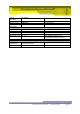
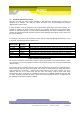
2 DOCUMENT REVISION
Issue
Amendment Details
Date of Issue
By
1
Initial Draft
23/12/2009
NK
2
DCR3006 – added section relating to test and
calibration procedures. Figures and Tables
identified using auto-numbered captions.
14/06/2010
SCH
3 FMCW OVERVIEW
3.1 Basic Operating Principles of FMCW Radar
In an FMCW radar such as the AGD315-205/207, the following basic operating principles are applied:
The transmit signal is frequency modulated, normally by a linear modulation (a chirp)
The modulation of the received signal is compared to the modulation of the transmitted signal to
determine time delay and therefore range
velocity is determined by range differentiation or Doppler processing
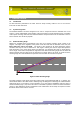
Consider a signal transmitted from the radar at time t=0 and with frequency f
start
. When this signal
strikes a target, the signal will be reflected back and received by the radar at a time t=t
delayed
. During
the time of flight of the reflected signal. the transmit frequency will have increased to a new frequency
f
delayed
, where f
delayed
is given by the chirp rate and amplitude.
Hence at any instance in time after t
delayed
, there is a difference in frequency between the transmitted
and received frequencies. This frequency difference is proportional to the time of flight for the
received signal, and since the radar signal travels at the speed of light (a constant), the time of flight is
also proportional to the range of the target which reflected the radar signal.
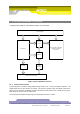
In an FMCW system, the transmit and receive signals are compared using an RF Mixer. The mixer is
driven by the transmit and receive signals, and the mixer output is the difference between the two
input signals. The output signal is referred to as the intermediate frequency (IF).
If the IF is sampled into an analogue to digital converter (ADC) at fixed time intervals during a single
excursion of the frequency modulation (one period of the chirp) and the resultant digital signal is
viewed in the frequency domain, a number of different frequencies will be seen, where each frequency
corresponds to a target at a particular range.
If data from a number of successive chirps is gathered and processed, speed and range for individual
targets can be determined.