
User Manual

,
© AGD Systems Ltd 2010. All rights reserved., the information contained in this document is the property of AGD Systems Ltd., and is supplied
without liability for errors or omissions. AGD315 User Manual Page 11 of 12
8 CABLE CONNECTIONS
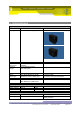
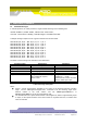
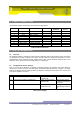
The AGD315-205/207 connections are shown in the table below:
Pin No.
Wire Colour
Function
Power Off
Power On -
No Detect
Power On -
Detect
1
Orange \ White
24v ac or 12-24v dc
2
White \ Orange
24v ac or 0v dc
3
Green
Earth / Ground
4
Blue \ White
Detector RS422 Y
5
Brown \ White
Relay Common
6
White \ Brown
Relay Contact
N/C
N/O
N/C
7
White \ Blue
Detector RS422 Z
8
White \ Green
Detector RS422 B
9
Green \ White
Detector RS422 A
Table 4 Cable Connections
9 TEST & CALIBRATION
9.1 Overview
The AGD315-205207 is subjected to rigorous build, calibration and test procedures. These procedures
are designed to provide a simple set of pass and fail criteria for production operatives to ensure
standardisation in the delivered product, isolate faults so they can be identified and fixed prior to unit
shipment, and to weed out infant mortality failures in components.
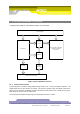
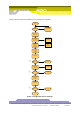
9.2 Configuration Of User Settings
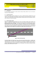
Once a unit has been calibrated, a number of specified settings are adjusted, and further tests are
carried out to ensure the unit is operating within acceptable limits (please refer to Figure 3 overleaf).
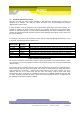
Table 5 summarises the user settings which are adjusted, showing the tests carried out, and the pass
\ fail criteria applied to each test.
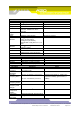
Test
Description
Pass \ Fail Limits
Comments
11
Check for correct operation of RS422
Receive OK
Transmit OK
At 115200 baud
12
Check serial number via RS422 port
Same as serial number
set previously
Serial number cannot
be adjusted via RS422
for security
13
Message OK
Frame rate 40FPS
Cosine set to 22º
Message should start
automatically on power
up
Table 5 User Settings