
Specifications

Not Used
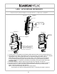
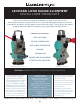
Back view
Figure 1
UB1 Universal Bracket
Bottom screw
Top screw
SETUP INSTRUCTIONS
x
MAY 2009
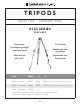
Figure 2
Shown Not aligned
Detector, strap, top and
bottom slides all slide up
or down to allow best
position for securing most
brands of detectors
Top slide
Bottom slide
Figure 3
Shown
aligned
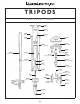
Loosen screws and spread top and bottom slides apart to make room for detector (Figure 1)
1.
Place detector in bracket. Align detector notch to top of pointer, move bottom slide up to detector
2.
and tighten screw. Move upper slide down to detector and tighten screw. (Fig. 2)
NOTE:
Not all detector notches will line up with pointer, it isn't required. Once the detector
is in the bracket the bracket pointer becomes the reference. Figure 2 What's important is
moving the detector in a position so that the top and bottom set screws will lock down their
respective slides
For thicker detectors, feed the strap through the upper slot and back over the top.
3.
For thinner detectors, feed the strap through the lower slot and back over the top. Figure 3
4.
Slide the strap up or down in the slots to the best location and secure as shown above.
5.
Figure 3 Shows bracket set up with detector.
Note
: In some cases the strap may rest over control buttons.
These buttons can still be activated through strap, or strap may be raised or lowered.
21