4/01ErNs511502 GasFiredCookers \@'9,-4 lnstallationlnstructionsfor Aga Gas PowerVent FiredRange Models:G.C.P.V.(2 Oven)N.G.and L.P'G. G.E.P.V.(4 Oven) (.e] For U.S.and CandianMarkets ANDTHEUSER BELEFTVMTHTHEAPPLIANCE SHOULD INSTRUCTIONS NOTE:THESEINSTALLATION REFERENCE. FORFUTURE TO RETAIN fof can be made,the siteis inspected TheGasfiredrangesarc deliveredunassembledBeforeinstallation codes local installation wiih conform to whefenecessary andcorrected .
W A L LT I L I N G shouldthetiles lfthe cookeris to standin a fecessor againsta wallwhichis to be tiled,in no circLlmstances overlapthe rangetop plate. GAS SUPPLY- U.S.PIPETHREADS LOCATIONlN THEGASPIPE lN AN ACCESSIBLE NOTE:A [4ANUALVALVElllUSTBE INSTALLED oF GASTo rHE oNoR SHUTTING oFTURNING FoRTHEPURPoSE Eiienrni io rne nppLrANcE APPLIANCE. ALL GASCONTROLSMUSTBE U.S.PIPETHREADS. Btu/h) Heatlnput4.4kW(15,000 Maximum The maximumgas inletpressureat the appliancemustnotexceed1o inchesw.g.
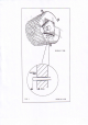
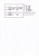
VENTSYSTEM whichcanreachupto 6 ventpipe50mm(2in)diameter discharge is bya fanpowered Products of combustion of 6 x 90' bendsor I metres(29ft)withonebendExitsfromthe metres(19.5fr) in lengththrough a Faximum sides,fromtherearcentreor fromtheunderside(Figs.2 & 3). appliance canbefromrearL.H.or-R.H. wallfixingplateby25mm( 1in)Fig.
D E S N5 1 1 1 8 9 F I G 1, DESN511126
rtt el ffic{lrhl ||!$ru ] EL S|l'E i gx !t o I I f,ffi tHtt^tsl al'lr: ml \rrfir ntr{N off xtE||n/rdr*l L,'1: lSilr$d€l,M nE|,|n& !3r t' ffi.TD Carejts|* t &€lrUrids ldar & *xs{ra$hn vArft !*hr&fig donlr6b. Wdng r.rq$ rawF ]rrpr.fllr qrd d!ng4|qf cp!|q!rj \is|ly frsrnl {rr'ldrrt als $dr6s.
l-*\o.
TERMINALPOSITION '1.The rangemustbe installedso thattheventterminalis exposedto the externalair andterminal clearancecomDlvwith: In l.r.s.:The NationalFuelGas CodesANSI22231 latesteditionSection7.7 installation code. In Canada:CAN/CGA-8149 2. Termination shouldbe on a clearexpanseofwall,the terminalbeingpreferablynotlessthan 355mm(14in)awayfroma corner,recessof projection'1.5"frominsideto outsidefaceof 3.
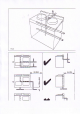
GCPV12ovElrtsl f*l]--';o,*o*o, qarsEo lrDsWHEN I i! I -T 'r 4Se#"1r' I ,i ti I rrtlr4tN,| I I tF=: I I Bl | I I | I| t4-:il | I L-_ I |lrilLlh= H l' l" Hil - T l| f lt r-,---J l t-- - lF tLI&::L=FJ +t l I 'Yr' I .,-N )n-,1* *1r1e-----* v#i?#..'-"- Tl ---J IINT PIPE V ,, / ./,/ / / / ,/ ,1"// ,/ ,/ ,/ ,/j/ / / , _* ^'cg::='t-Uil I| l" /\ | I P,] //'="'\'l ?. I \t I// , t urlsi=ffilbr vEr.rT PrPE ll \ 6l l{, j|l' )lW I \"-// \=d/ II l" Z I "l| V , t l.
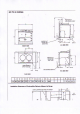
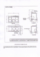
cE PV(1OVENS| ouT t|,rocK HO|.:S fOB VENTPIPE Llr.8&€\4rv nn "V\"/. GASCONrrlEmONA.H. i.r{. 6DEV|EW c mm148796? 851 n F 41 1314 K L M N P o R s 3S 3 698 65 375 48 595 1 1 6 68 J LOCATIONOF NAMEPLATE The modelandserialnumbersfor thisapplianceare foundon the nameplate.Thesenumbersrn!st be used Thenameplateis locatedon the insideof the outefburner whenrequesting advicefromyoufAga Distributor. door.
REMOVE COVER TO LOCATE C COMMISSIONING LIGHTINGTHEBURNER- (Erg4) NOSMOKING OR NAKEDLIGHTS CAUTION: valve. Openthe burnerouterdoorto exposethe gas controlcombination CAUTION:BEFORELIGHTINGENSURETHATTHEGASVALVEKNOB2 lS SETIN THEOFFPOSITION. ON. (SEEEIG.A)AND THEELECTRICAL SUPPLYTO THEAGA IS SWITCHED '1.Turnoff uniongas cock1. Testthe gas installation fromthe metercockfof soundnessand puqe to the 2. Turnon gassupplyto cookerand opengas cock1. 3.
i\ ,ru. OFF { rGNrroN FIGB WHTTE BLOCK LOWFIRE FIGC n-- BAND GREEN NORMALRUNNING 6. After30 minutes,checkthe burnergas pressure. {i) Turnthegas controlknob2 to PILOTposition{seeFjg'B) Removethe mainburnefpressuretestnippleplug5 andfit pressuregauge.Turngasvalvecontrolknob2 to the mid positionofthe grcenband. to thedataplate.
plug.Tum temperature controlknob2 to the mid positionofthe greenbandfor normalrunning mayrundown 7. On the firstlightingor if the cookerhas beencoldfor a longtime,moisturcfromthe insulation prevent staining. be wiped ofito ofthe cooker. This should the enamelled front to maintainthe cookerat the heatcontrolwilloperateautomatically Oncethe corect settinghas beenconfirmed fulltempe€turc.
./'-.--"\.t.
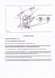
YEARLYSERVICE thatthe rangebe servicedevery12 months. It is recommended Arrangewiththe housholder thatthe rangel"rasbeenturnedOFFthe nightbeforeto ensureit is colduponaadval. ElectricSupplybeforeservicing. 1. WARNING:Disconnect gasvalve.Breakthe 2. lsolatethe gas supplyby turningoff the seNicegasvalvebeneaththe combination nut. heaxgonunionconnection 3. Detachthe innerburnerdoorfixingscrewanddrawcompletegas burnerassemblyclearofthe combustion chamberrestingit on the floorofthe range.
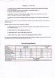
ln the eventofa component failurewhichrequiresrcplacement, contactyourlocalAga distributor whowilladvise and supplythe necessaryreplacement. Expendable components thatwill requirereplacingat sometimeor otherare listedas fo ows: Description '. PilorThermocouple 2. lvlainBurner 3a.PilotBurnerAssembly N_G. 3b.PilotBurner Assembly L.P.G. 4. Combustion GasValve 5a. PressureRegulatorN.G. 5b. PressureRegulatorL.P.c. 6. Combustion ChamberDoorSeal 7. SolenoidGasValve 8. VentingFan 9.