GC 3 (PF) (THREE OVEN) GAS FIRED POWER FLUE COOKER Installation Instructions REMEMBER: when replacing a part on this appliance, use only spare parts that you can be assured conform to the safety and performance specification that we require. Do not use reconditioned or copy parts that have not been clearly authorised by AGA.
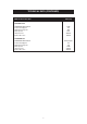
CONTENTS SECTION PAGE HEALTH & SAFETY 3 INSTALLATION 4 LOCATION 4 TECHNICAL DATA 5-7 FLUE SYSTEM 8 - 11 AIR SUPPLY 12 INSTALLATION PIPES 12 BAKING OVEN BAFFLE PLATE 12 ELECTRICAL 12 COMMISSIONING - USING CONTROL KNOB WITH NUMBERED GRAPHICS 13 - 15 COMMISSIONING - USING CONTROL KNOB WITH GREEN BAND GRAPHICS 16 - 18 2
HEALTH & SAFETY Consumer Protection As responsible manufacturers we take great care to make sure that our products are designed and constructed to meet the required safety standards, when properly used and installed. IMPORTANT NOTICE: PLEASE READ THE ACCOMPANYING WARRANTY. Any alteration that is not approved by AGA could invalidate the approval of the appliance, operation of the warranty and could affect your statutory rights. Important This appliance may contain some of the materials that are indicated.
INSTALLATION With specific exceptions, the installing of any type of AGA cooker is subject to the respective directions contained in current issue of the Building Regulations. In addition, Planning Permission may need to be obtained, which should be applied for separately. The complete range of AGA cookers are suitable for Natural or Propane gases only and cannot be used on any other gas. (IMPORTANT: See data plate which is situated on burner housing panel behind top left door).
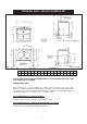
TECHNICAL DATA - AGA GC3 (POWER FLUE) FIG. 1 DESN 513391B A B C D E F G H J K mm 987 967 851 679 41 1330 756 1125 39 3 L R S 698 116 48 T U V 65 375 595 667 PLEASE NOTE: SIDE CLEARANCE DIMENSION R IS ALSO REQUIRED ON THE LH SIDE FOR THE BAKING OVEN DOOR. COOKER DIMENSIONS When surveying for a cooker installation the actual clearance required for the ‘body’ of the appliance should be increased overall by 10mm beyond the figures quoted below.
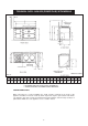
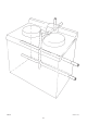
TECHNICAL DATA - AGA GC3 (POWER FLUE) WITH MODULE DESN 513392 B FIG.
TECHNICAL DATA (CONTINUED) Models GC3 Power Flue GC3 (PF) NATURAL G20 MAXIMUM HEAT INPUT Thermostat Bypass Main Burner Injector Pilot Injector Inlet Pressure Burner Pressure 5kW 110 400 4212 20mbar 10mbar PROPANE G31 5kW (357g/h) 65 170 4209 37mbar 25mbar MAXIMUM HEAT INPUT Thermostat Bypass Main Burner Injector Pilot Injector Inlet Pressure Burner Pressure 7
FLUE SYSTEM SEE FIGS. 2, 3, 4 & 5 The flue system must be installed in accordance with the regulations in force. Products of combustion discharge is by a fan powered flue pipe of 50mm diameter which can reach up to 6 metres in length through a maximum of 6 x 90Þ bends or 9 metres with one bend. Exits from the appliance can be from rear LH or RH sides, from the rear centre or from the underside (See Figs. 4 & 5). The flue pipe should exit through the outside wall fixing plate by 25mm (Fig. 2).
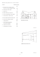
Minimum siting dimensions for Flue terminals Position Minimum Spacing mm A Directly below an openable window, air vent, or an other ventilation opening 300 B Below gutter, drain/soil pipe 75 C Below eaves 200 D Below a balcony or car port roof 200 E From vertical drain pipes and soil pipes 150 F From internal or external corners 200 G Above adjacent ground or balcony level 300 H From surface facing the terminal 600 I Facing terminals 1200 J From opening (door/window) in car por
DESN 511190 FIG.
DOWNWARD RUNS UP TO 300mm BELOW THE APPLIANCE ARE ALLOWED, PROVIDED ONLY ONE BEND IS USED. DOWNWARD RUNS USING 2 BENDS ARE NOT ALLOWED. DESN 511191 FIG.
AIR SUPPLY Kitchen or Internal Space Air Supply The appliance can only be installed in a room which meets ventilation regulations in force but in any event the room must have a permanent vent of minimum free air of of 36cm2. INSTALLATION PIPES Installation pipes should be fitted in accordance with current Gas Regulations. Pipework from the meter to the cooker must be of adequate size, cooker connection size of 15mm Dia.
COMMISSIONING NOTE: FOR MODELS WITH NUMBERED GRAPHICS ON CONTROL KNOB ‘B’ (SEE FIG. 7 & 8) CAUTION: BEFORE LIGHTING: ENSURE KNOB (A) IS IN THE OFF POSITION (SEE FIG. 9). ALSO ENSURE GAS SUPPLY TO COOKER IS ON, AND THE GAS SERVICE COCK (C) IS IN THE ON POSITION (SEE FIG. 7), AND THE ELECTRICAL SUPPLY TO THE AGA IS SWITCHED ON. LIGHTING PROCEDURE - SEE FIGS 8 - 13 1. The main burner gas flow is set with the temperature knob (B) (See Fig. 8).
COMMISSIONING (CONTINUED) 7. Check burner pressure as follows:Repeat instruction 6 on completely cold cooker with the pressure gauge fitted to the burner pressure test nipple (E) (See Fig. 7). Check that the burner pressure correctly corresponds with the table marked ‘TECHNICAL DATA’, (page 7). NOTE: IF FOR ANY REASON A GAS RATE CHECK IS REQUIRED. TURN OFF ALL OTHER APPLIANCES USING GAS AND USING THE GAS METER TEST DIAL AND STOPWATCH.
BURNER CONTROLS 15
COMMISSIONING NOTE: FOR MODELS WITH GREEN BAND GRAPHICS ON CONTROL KNOB ‘B’. (SEE FIGS. 14 & 15) CAUTION: BEFORE LIGHTING: ENSURE KNOB (A) IS IN THE OFF POSITION (SEE FIG. 16). ALSO ENSURE GAS SUPPLY TO COOKER IS ON, AND THE GAS SERVICE COCK (C) IS IN THE ON POSITION (SEE FIG. 14), AND THE ELECTRICAL SUPPLY TO THE AGA IS SWITCHED ON. LIGHTING PROCEDURE: SEE FIGS. 15 - 21. 1. The main burner gas flow is set with the ‘temperature’ knob (B) (See Fig. 15). First, ensure both knobs are turned fully clockwise.
COMMISSIONING (CONTINUED) 7. Check burner pressure as follows:Repeat instruction 6 on completely cold cooker with the pressure gauge fitted to the burner pressure test nipple (E). (See Fig. 14). Check that the burner pressure correctly corresponds with the table marked ‘TECHNICAL DATA’, (page 7). NOTE: IF FOR ANY REASON A GAS RATE CHECK IS REQUIRED. TURN OFF ALL OTHER APPLIANCES USING GAS AND USING THE GAS METER TEST DIAL AND STOPWATCH.
BURNER CONTROLS FIG. 15 FIG. 16 FIG. 17 FIG. 18 FIG. 19 FIG. 20 FIG.
For further advice or information contact your local AGA Specialist With AGA’s policy of continuous product improvement, the Company reserves the right to change specifications and make modifications to the appliance described and illustrated at any time Manufactured by AGA Station Road Ketley Telford Shropshire TF1 5AQ England www.aga-web.co.uk www.agacookshop.co.uk www.agalinks.