GC 3 (THREE OVEN) Installation Instructions REMEMBER: when replacing a part on this appliance, use only spare parts that you can be assured conform to the safety and performance specification that we require. Do not use reconditioned or copy parts that have not been clearly authorised by AGA.
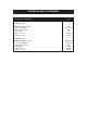
CONTENTS SECTION PAGE HEALTH & SAFETY 3 INSTALLATION 4 LOCATION 4 TECHNICAL DATA - 3 OVEN AGA (GC3) ONLY 5 TECHNICAL DATA - 3 OVEN AGA WITH MODULE (GC3M) 6 TECHNICAL DATA - CONTINUED 7 FLUE SYSTEM 8 INSTALLATION PIPES 8 AIR SUPPLY 8 BAKING OVEN BAFFLE PLATE 8 COMMISSIONING 9 - 11 INSTRUCTIONS 11 2
HEALTH & SAFETY Consumer Protection As responsible manufacturers we take care to make sure that our products are designed and constructed to meet the required safety standards when properly installed and used. IMPORTANT NOTICE: PLEASE READ THE ACCOMPANYING WARRANTY. Any alteration that is not approved by AGA could invalidate the approval of the appliance, operation of the warranty and could affect your statutory rights. Important This appliance may contain some of the materials that are indicated.
INSTALLATION With specific exceptions, the installing of any type of AGA cooker is subject to the respective directions contained in current issue of The Building Regulations. In addition, Planning Permission may need to be obtained, which should be applied for separately. The complete range of AGA cookers are suitable for Natural or Propane gases only and cannot be used on any other gas. (IMPORTANT: See data plate which is situated on burner housing panel behind top left door).
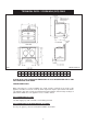
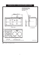
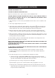
TECHNICAL DATA - 3 OVEN AGA (GC3) ONLY FIG. 1 DESN 512841 B A B C D E F G H J K L M N mm 987 889 851 679 467 1035 41 1330 756 1125 73 39 3 P W 698 116 PLEASE NOTE: SIDE CLEARANCE DIMENSION W IS ALSO REQUIRED ON THE LH SIDE FOR THE BAKING OVEN DOOR. COOKER DIMENSIONS When surveying for a cooker installation the actual clearance required for the ‘body’ of the appliance should be increased overall by 10mm beyond the figures quoted below.
TECHNICAL DATA - 3 OVEN AGA WITH MODULE (GC3M) FIG. 1A - GAS SUPPLY CONNECTIONS (APPROXIMATE POSITIONS) NOTE: 1/4” BSP to 15mm fitting provided.
TECHNICAL DATA (CONTINUED) Models GC3 Standard Flue GC3 NATURAL G20 MAXIMUM HEAT INPUT Thermostat Bypass Main Burner Injector Pilot Injector Inlet Pressure Burner Pressure 5kW 100 or 120 400 4212 20mbar 10mbar PROPANE G31 5kW(357g/h) 60 or 80 170 4209 37mbar 25mbar MAXIMUM HEAT INPUT Thermostat Bypass Main Burner Injector Pilot Injector Inlet Pressure Burner Pressure 7
FLUE SYSTEM The following notes are intended to give general guidance:The initial length of flue pipe from the appliance flue socket should be vertical for at least 600mm. In any event, the minimum flue length must not be less than 3m. The cross-sectional area of the flue serving the cooker must not be less than the area of the flue outlet of the cooker. If the flue pipe is to be used then, it must not be less than 100mm internal diameter.
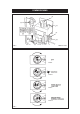
COMMISSIONING (2) (6) (3) (5) (4) FIG. 2 (1) DESN 512431 FIG. A FIG. B FIG. C FIG. D FIG.
COMMISSIONING (CONTINUED) LIGHTING THE BURNER - FIG. 2. CAUTION: NO SMOKING OR NAKED LIGHTS Open the outer burner door to expose the gas control combination valve. CAUTION: BEFORE LIGHTING: ENSURE THAT THE GAS VALVE CONTROL KNOB 2 IS SET IN THE OFF POSITION (SEE FIG. 3A) AND COMBUSTION DISCHARGE SAFETY DEVICE BUTTON 6 IS DEPRESSED. 1. Turn off union gas cock 1. Test the gas installation from the meter cock for soundness and purge. 2. Turn on gas supply and open gas cock 1. 3.
COMMISSIONING (CONTINUED) 9. Check burner pressure as follows:Repeat instructions 8 on completely cold cooker with the pressure gauge fitted to the burner pressure test point 5. Check that the burner pressure correctly corresponds to the table on page 6. NOTE: IF FOR ANY REASON A GAS RATE CHECK IS REQUIRED, TURN OFF ALL OTHER APPLIANCES USING GAS, AND USING THE GAS METER TEST DIAL AND A STOP WATCH, CHECK THAT THE MAXIMUM GAS INPUT TO THE APPLIANCE IS AS INDICATED ON THE DATA PLATE.
For further advice or information contact your local AGA Specialist WithAGA’s policy of continuous product improvement, the Company reserves the right to change specifications and make modifications to the appliance described and illustrated at any time Manufactured by AGA Station Road Ketley Telford Shropshire TF1 5AQ England www.aga-web.co.uk www.agacookshop.co.uk www.agalinks.