COMPANION/MODULE (with Gas Hob) OWNERS MANUAL WARNING: If the information in this manual is not followed exactly, a fire or explosion may result causing property damage,personal injury or death. Do not store or use gasoline or other flammable vapors and liquids in the vicinity of this or any other appliance. WHAT DO YOU DO IF YOU SMELL GAS . Do not try to light any appliance. . Do not touch any electrical switch . Do not use any phone in your building. .
CONTENTS SECTION PAGE INSTALLATION 3 LOCATION 4 PRODUCT DIMENSIONS - COMPANION 5 PRODUCT DIMENSIONS - MODULE 6 INSTALLATION CLEARANCE OF COMBUSTIBLE CABINETS 7 TECHNICAL DATA 8 INSTALLATION 9-15 INSTALLATION - MODULE ONLY 10 ELECTRICAL CONNECTIONS 16-17 CONNECTING TO GAS - COMPANION 18 PRESSURE TESTING 19 SERVICING - COMPANION & MODULE 20-27 USERS GUIDE 28 INTRODUCTION 29 SAFETY PRECAUTION AND HINTS 30 APPLIANCE VIEW 31 CONTROL PANEL 32 GAS HOTPLATE 33-34 THE GRILL & OV
Installation Section Remember, when replacing a part on this appliance, use only spare parts that you can be assured conform to the safety and performance specification that we require. Do not use reconditioned or copy parts that have not been clearly authorised by Aga-Ranges.
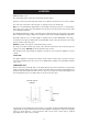
LOCATION REFER TO FIG 1 & 2 The side wall clearance above the hob shall be greater than 3”. Surfaces over the top of the range must not be closer than 28” and must not exceed 13” in depth. The vent slots in the back of the top plate (or shroud) must not be obstructed. Note: It is essential that the supply cable is routed away from any hot surfaces i.e. hot flue pipes. In the interests of safety, due consideration must be given to the protection of the electric cable to the Module/Companion.
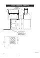
PRODUCT DIMENSIONS - COMPANION 330mm MAX. (13”). OVERHEAD CUPBOARD 711mm MIN. (28”) 75mm (3”) 948mm (373/8”) (3”) 595mm (231/2”) 600mm (233/4”) 910mm (35 3/4”) 75mm 680mm (263/4”) (421/2”) 1080mm APPLIANCE CAN BE CLOSE FITTED TO KITCHEN UNITS UP TO WORK TOP HEIGHT.
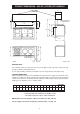
PRODUCT DIMENSIONS - AGA GC (2-OVEN) WITH MODULE OVERHEAD CUPBOARD POSITION OF LIDS WHEN RAISED E A E P N Q G F B O C L D M H J OVEN DOOR IN OPEN POSITION K Fig 2 DESN 511633 MODULE ONLY:The extension channel section at the rear of each side plate may be removed, if required to clear flue pipes with the following provisions:A 2” air gap should be provided on left hand side of the range (Power Vent models only) COOKER DIMENSIONS When surveying for a range cooker installation the actual clea
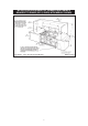
INSTALLATION CLEARANCES OF COMBUSTIBLE CABINETS ADJACENT TO RANGE (GC3 (3 OVEN) WITH MODULE SHOWN) Fig 2A GC3 - Open Flue Model (with Module) 7 DESN 512438
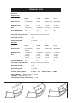
TECHNICAL DATA HOTPLATE NATURAL GAS R.H.F. L.H.R. R.H.R. L.H.F. BURNER TYPE ULTRA RAPID (WOK) RAPID SEMI-RAPID SEMI-RAPID MAXIMUM HEAT INPUT 3.5 kW 12,000 Btu/hr 3.1 kW 10,600 Btu/hr 1.8 kW 6,150 Btu/hr 1.8 kW 6,150 Btu/hr INJECTOR MARKING 170 155 118 120 PRESSURE POINT POSITION: FRONT LH HOTPLATE INJECTOR PRESSURE SETTING: 4” wg BURNER IGNITION: H.T. SPARK PROPANE R.H.F. L.H.R. R.H.R. L.H.F.
INSTALLATION CAUTION: THIS INSTALLATION MUST CONFORM WITH LOCAL CODES OR, IN THE ABSENCE OF LOCAL CODES WITH THE NATIONAL FUEL GAS CODE, ANSI Z223.I AND NATIONAL ELECTRICAL CODE ANSI/NFPA 70 (IN CANADA CAN/CGA-B149) AND ONLY USED IN A WELL VENTILATED SPACE, READ THESE INSTRUCTIONS BEFORE INSTALLING OR USING THIS APPLIANCE. PRIOR TO INSTALLATION, ENSURE THAT THE LOCAL DISTRIBUTION CONDITIONS (NATURE OF GAS AND GAS PRESSURE) AND THE ADJUSTMENTS OF THE APPLIANCE ARE COMPATIBLE.
INSTALLATION - MODULE ONLY Having ensured all space requirements and regulations have been satisfied for the combined arrangement (Aga Cooker and Module), the build and installation is to proceed as follows:1. It is essential that a base or hearth on which both cooker and module stands should be level and capable of supporting the total weight of both units. Module weight = 129kgs (284 lbs) 2. Unpack and remove the Module from the pallet. 3. Remove top plate as follows:a) b) c) d) e) 4.
9. Levelling of the Simmering Plate on the main cooker can be carried out with its top plate in position and verified across the Module (See Fig. 7). 10. Complete the main cooker build and loosely screw down the top plate. 11. Apply tape (provided) to the underside of the lap strip on the Module top plate. 12. Replace module hotplate. Reassemble in reverse order (See section 4). Ensure burner heads and burner caps are correctly located (See Fig. 8A, 8B and 8C) and electrodes are not damaged. 13.
OFF REMOVE 2 FIXING SCREWS DESN 511645 Fig 3 (WOK BURNER ONLY) DESN 511646 Fig 4 12
(311/2”) mm (2 3/8 ”) mm (22 1/4 ”) mm mm (1”) DESN 511647 Fig 5 - Gas Supply Connections NOTE: A special rubber grommet is provided to fill-in the ‘knock-out’ hole in the side panel. Pierce the centre of the grommet and pass the 1/4” gas supply pipe through it.
mm (5/8”) DESN 511254 Fig 6 (2 1/2”) 64mm FROM TOP SURFACE OF THE AGA TO LUGS ON FRONT PLATE OF MODULE mm TOP PLATE OF MODULE REMOVED DESN 511255 Fig 7 14
BURNER CAP RETAINING LUGS DESN 511617 Fig 8A BURNER CAP BURNER HEAD ELECTRODE DESN 511618 Fig. 8B BURNER CAP BURNER RING BURNER HEAD (WOK BURNER ONLY) ELECTRODE Fig.
ELECTRICAL CONNECTIONS Electric Shock Hazard Electrical grounding is required on this range. Do Not connect to the electrical supply until the range is permanently grounded. Disconnect the power to the junction box before making the electrical connection. This range must be connected to a grounded, metallic, permanent supply or a grounding connector should be connected to the grounding terminal or wire lead on the range. Do Not ground to gas pipe.
6. Remove the terminal block cover screws located on the back of the range. 7. Make the four-wire connection following the “Power supply cord method”. Power supply cord method This range is manufactured to use a four-wire power supply cord rated at 250-volts, 30-amperes (See “Four wire electrical connection”) L2 L1 WHITE (NEUTRAL) GREEN (GROUND) Fig. 9 1. 2. 3. 4. DESN 511752 Assemble a U.L.-listed strain relief in the opening.
CONNECTING TO GAS - COMPANION CAUTION: ENSURE THAT COOKER IS ISOLATED FROM ELECTRIC SUPPLY The cooker can be installed with an approved flexible connection. Supply piping should not be less than 3/8 I/D Flexiline. Connection is made to the 1/2” NPT female threaded elbow located just below the hotplate level on the near left hand side of the cooker. 2 m 00m (77/8 ”) 558mm (22”) 279mm (11”) 390mm (151/4”) 480mm (187/8”) TERMINAL BLOCK COVER ”) m 60m (18 4 22 m( 1/2 ”) m 573 Fig.
PRESSURE TESTING The maximum gas inlet pressure to the appliance must not exceed 12” wg for N.G. and 14” for L.P. Gas. The minimum gas inlet pressure at the appliance must not be less than 4” w.g. Natural Gas and 10” wg L.P. Gas to enable the correct manifold pressure to be obtained. NOTE: The regulator is pre-set for either N.G. or L.P. Gas. Use the small hotplate burner injector as the pressure test point. For Natural Gas manifold pressure is 4” w.g. For L.P.G. (Propane Only) manifold pressure 10” w.g.
AGA COMPANION/MODULE (with Gas Hob Unit) SERVICING NOTES DISCONNECT FROM ELECTRICITY SUPPLY BEFORE SERVICING. WHEN REWIRING ANY ELECTRICITY COMPONENTS REFER TO CIRCUIT DIAGRAM AND ELECTRICAL SCHEMATIC DIAGRAM ATTACHED BEFORE ELECTRICAL RECONNECTION. CHECK THAT THE APPLIANCE IS ELECTRICALLY SAFE. NOTE: TURN OFF GAS SUPPLY TO COOKER BEFORE SERVICING ANY GAS CARRYING COMPONENTS. ALWAYS CHECK APPLIANCE FOR GAS SOUNDNESS AFTER COMPLETION. NOTE: USE SOAPY WATER SOLUTION TO ENSURE THERE ARE NO GAS LEAKS A.
D. TO CHANGE IGNITION ELECTRODE 1. 2. 3. 4. 5. 6. Turn off electricity supply. Remove Top Plate and Hotplate (See sections A and B). Disconnect the electrode cable from the ignition generator. Remove spring clip retaining electrode to burner body (See Fig. 13) and remove electrode and cable. Replace with new electrode ensuring spring clip is correctly located into burner body. Re-assemble in reverse order and check operation of ignition to hotplate burners. E. TO CHANGE HOTPLATE GAS TAP 1. 2. 3. 4. 5.
DESN 511792 SPARK GENERATOR TERMINAL BLOCK Fig.
Fig. 13 DESN 511649 Fig.
GAS RAIL SUPPORT BRACKET SCREWS GAS RAIL TUBE NUT GAS RAIL SUPPORT BRACKET SCREWS GAS TAP TUBE NUT Fig. 15 DESN 511651 Fig.
NOTE: 1. IGNITION SWITCHES AND THERMOSTATS ARE SHOWN IN THE OFF POSITION WITH THE APPLIANCE COLD AND FAN OVEN DOOR IS CLOSED. 2. THE COOKER IS COLD (IE. CUT-IN & CUT-OUT NOT OPERATED) CAUTION: LABEL ALL WIRES PRIOR TO DISCONNECTION WHEN SERVICING CONTROLS WIRING ERRORS CAN CAUSE IMPROPER AND DANGEROUS OPERATION.
HANDRAIL FITTING - MODULE ONLY JOINTING BRACKET GASKET SILICON STRIP JOINTING BRACKET COOKER HANDRAIL END CAP (4) HOT CUPBOARD HANDRAIL FIBRE PROTECTION WASHERS (2) FIBRE WASHERS (2) SOCKET SCREWS (2) END BRACKET (2) JOINTING BRACKET FIXING PLATE Prior to fitting the cooker top plate and hot cupboard/electric module top plate to the appliance:z z z z Ensure the self adhesive silicone strip is fitted to the underside of the hot cupboard/electric module overlap to protect the enamel and the jointi
Users Guide 28
INTRODUCTION As responsible manufacturers we take care to make sure that our products are designed and constructed to meet the required safety standards when properly installed and used. IMPORTANT NOTICE: PLEASE READ THE ACCOMPANYING WARRANTY. Any alteration that is not approved by Aga could invalidate the approval of the appliance, operation of the warranty and could affect your statutory rights. In the interests of safety and effective use, please read the following before using your new Aga appliance.
SAFETY PRECAUTION AND HINTS 1. Do not store combustible materials, gasoline or other inflammable vapors and liquids near a range cooker. 2. Ensure and maintain the continual free passage of air to the burner housing. Do not stand obstacles against burner outer door and loose hair from dogs or cats must not be allowed to accumulate behind the outer burner door. Child Safety Children MUST be taught safe range practices to prevent possible injury.
SEMI RAPID BURNER GAS HOTPLATE RAPID BURNER WOK BURNER SEMI RAPID BURNER CONTROL PANEL REMOVABLE LINER GRILL PAN WITH GRID GRILL & CONVENTIONA L OVEN GRID SHELF FANNED OVEN ROASTING TIN (BAKING TRAY NOT SHOWN) FOR USE IN BOTH OVENS DESN 511635 Fig 17 31
CONTROL PANEL GAS HOB BURNERS REAR LEFT FRONT LEFT REAR RIGHT FRONT RIGHT GRILL TOP OVEN LOWER OVEN OFF TOP OVEN NEON LOWER OVEN NEON DESN 511620 Fig. 18 z The GAS HOTPLATE CONTROL KNOBS can only be rotated anti-clockwise from the OFF position. Large Flame Symbol - High Setting Small Flame Symbol - Low Setting (See ‘HOTPLATE’ section). z The GRILL ELEMENT KNOB can be rotated in any direction.
GAS HOTPLATE z The hotplate has four gas burners:rear left - rapid burner - rated at 3.25 kW/11,000 Btu/hr front left and rear right - semi rapid burner - each rated at 1.8 kW/6,150 Btu/hr front right - ultra rapid (wok) burner - rated at 3.5 kW/12,000 Btu/hr z The semi rapid burners are especially suited for use with small pans and for gentle simmering or poaching. z All burners have a set simmer position and are easily adjustable.
Deep Fat Frying z Use a deep pan large enough to completely cover the appropiate heating area. z Never fill the pan more than one-third full of fat or oil. z Never leave fat or oil unattended during the heating or cooking period. z IMPORTANT: Oil is a fire risk, do not leave pans containing oil unattended. z In the event of a fire cover with a lid and turn OFF the appliance. Do not attempt to extinguish the fire using water.
THE BROILER (TOP OVEN) z THE TOP OVEN DOOR MUST BE KEPT OPEN WHEN THE GRILL IS ON. z CAUTION: Accessible parts may be hot when the grill is in use. Young children should be kept away. z The grill has 5 heat settings on each of 2 elements (see control panel). z For best results pre-heat at a high setting. z The large grill pan and grid supplied will fit on any of the three shelf positions. z Most foods should be cooked on the grill rack in the grill pan.
z DO NOT TOUCH HEATING ELEMENTS OR INTERIOR SURFACES OF OVEN - Heating elements may be hot even though they are dark in colour. Interior surfaces of an oven become hot enough to cause burns. During and after use, do not touch, or let clothing or other flammable materials contact heating elements or interior surfaces of oven until they have had sufficient time to cool.
OVEN COOKING GUIDE Cooking Hints z Pre-heat selected oven until the neon light goes out. z The guidelines are for cooking after the oven (s) have reached the desired temperature. z Larger items may benefit from being turned. z Shelf positions are counted from the top. z Put dishes in the centre of the shelf. z When using both ovens together reduce cooking times and settings. z It is important to check that food is piping hot before serving.
Top Oven (Conventional) Top Oven (Conventional) • Top Oven (Conventional) • Top Oven (Conventional) z The cooking charts are a general guide but times and temperatures may vary according to individual recipes. z The meat sections should be used as a guide but may vary according to the size, shape of meat on or off the bone. z Thaw frozen pieces of meat thoroughly before cooking them. z The times are for open roasting. If covered with foil allow extra time.
Top Oven (Conventional) • Top Oven (Conventional) • Top Oven (Conventional) • Top Oven (Conventional) • Top Oven (Conventional) SETTING °F SHELF POSITION 300 2 45 mins - 1 hr Very Rich Fruit Cake 250/275 3 3 - 4 hrs Fruit Cake 300/325 3 1 - 2 hrs Small Cakes 375 3 15 - 25 mins Scones 425 3 10 - 20 mins Victoria Sandwich 350 3 20 - 35 mins Swiss Roll 410 2 10 mins 350/375 2 10 - 15 mins 350 3 30 - 35 mins Plate Tarts 400 2 25 - 35 mins Fruit Pie 400 3 35 - 45 mins
Lower Oven (Fanned/Convection) Lower Oven (Fanned) • Lower Oven (Fanned) z The lower oven is fanned or a convection oven, which means the air is circulated to create an even temperature throughout the oven. In most cases this means that food requires a lower temperature when cooked in this oven, by approximately 10º (18ºF) - 20ºC (36ºF). Also some baked goods may require a slightly reduced cooking time by a few minutes.
Lower Oven (Fanned) • Lower Oven (Fanned) Lower Oven (Fannned) • Lower Oven (Fanned) Lower Oven (Fanned) SETTING °F SHELF POSITION 275 2 or 3 45 - 50 mins Very Rich Fruit Cake 250/275 3 3 - 4 hrs Fruit Cake 275/300 3 1 - 2 hrs Small Cakes 350 Any 15 - 25 mins Scones 400 Any 8 - 12 mins Victoria Sandwich 325 Any 20 - 35 mins Swiss Roll 400 2 10 mins 325/350 Any 10 - 15 mins 325 3 25 - 30 mins Plate Tart 375 2 or 3 25 - 35 mins Fruit Pie 375 2 or 3 25 - 45 mins Minc
CLEANING & CARING FOR YOUR COOKER z Always switch OFF at mains before cleaning. z When cleaning use as little water as possible. z Do not use a steam cleaner to clean this range. z Do not use abrasive pads, oven cleaner, or cleaners containing citric acid on enamelled surfaces. Surfaces that require cleaning are: Enamelled Top and Front z The easiest way to clean the Aga Companion/Module top and front plate is to mop up spills as they happen.
Heat-Clean Enamel z Fan Oven, Conventional Oven, Simmering Oven: sides, top and back Grill Compartment: sides and back This special enamel has a continuous cleaning action, which works best if a pattern of low and high temperature cooking is followed. By using low temperature roasting, excessive fat splashes can be avoided. Should any excessive staining occur, immediately clean the area with hot water containing detergent, and a nylon washing-up brush.
BURNER CAPS RETAINING LUGS DESN 511617 Fig 19A BURNER CAP BURNER HEAD ELECTRODE DESN 511618 Fig 19B BURNER CAP BURNER RING BURNER HEAD ELECTRODE DESN 511619 Fig 19C- WOK BURNER ONLY 44
SERVICING z In the event of your appliance requiring maintenance, please contact your authorised distributor. z Your cooker must only be serviced by a Qualified Engineer, from an authorised distributor . z Do not alter or modify the cooker. z Only the spares specified by the manufacturer, are to be fitted.
For further advice or information contact your local distributor/stockist With Aga’s policy of continuous product improvement, the Company reserves the right to change specifications and make modifications to the appliance described and illustrated at any time. Aga-Ranges 110 Woodcrest Road Cherry Hill, NJ 08003 USA 800.633.9200 www.aga-ranges.