
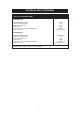
Technical data

5
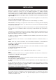
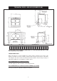
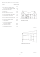
TECHNICAL DATA - AGA GC3 (POWER FLUE)
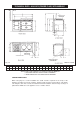
Fig. 1 DESN 513391B
ABCDEFGHJKLRSTU
VW
mm
987
967 851 679 41
1330
756 39
3
698 116 48 65 375 595 667
1125
PLEASE NOTE: SIDE CLEARANCE DIMENSION R IS ALSO REQUIRED ON THE LH SIDE
FOR THE BAKING OVEN DOOR.
COOKER DIMENSIONS
When surveying for a cooker installation the actual clearance required for the ‘body’ of the
appliance should be increased overall by 10mm beyond the figures quoted above. This allows
safe margin to take into account the natural dimensional variations found in major castings. In
particular the width across the appliance could be critical.
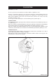
GAS CONNECTION GC3 POWER FLUE ONL
Y
1/4” BSP supply pipe, with 1/4” BSP to 15mm fitting provided.
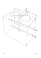
GAS CONNECTION GC3 POWER FLUE WITH
A
MODULE (IF FITTED)
See Fig. 1A, and refer to Module Installation Instructions.