
Technical data
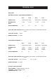
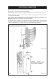
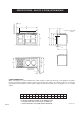
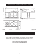
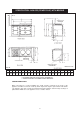

SPECIFICATIONS - AGA GC (2 OVEN) WITH MODULE
7
ABCD
E
F* G H J K L M
N
**
O
**
mm
1598
889 851 679 60
967 1330 756
1125
116
3 698
1533
800
FIG. 2
* ELECTRIC AND GAS POWER FLUE MODELS ONLY
** POSITION FOR GAS SUPPLY PIPE TO MODULE
*** WHEN ADJACENT TO COMBUSTIBLE MATERIAL
DESN 511633
E
A
N
C
G
B
O
L
D
F
H
J
K
M
OVEN DOOR IN
OPEN POSITION
POSITION OF LIDS WHEN
RAISED
COOKER DIMENSIONS
When surveying for a cooker installation the actual clearance required for the ‘body’ of the appliance should be
increased overall by 10mm beyond the figures quoted below. This allows safe margin to take into account the
natural dimensional variations found in major castings. In particular the width across an appliance recess could be
critical.
***