
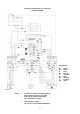
Technical data
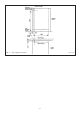
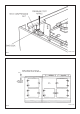


8. Make final gas connection to the cooker (15mm compression) into the combined gas
cock/pressure test fitting (See Fig. 7). Check for gas tightness after connecting the gas
supply.
9. PRESSURE TESTING
The pressure test point is situated at the rear left hand side of the appliance just below
hotplate level. (See Fig. 7).
Remove screw from pressure test nipple. Fit the pressure gauge onto the pressure test
nipple.
Turn the gas cock to the ON position.
Place one of the burner heads and burner cap into position on the burner body. Push in and
turn the appropriate control knob anti-clockwise to full-on position, and light the burner
with a match.
For Natural Gas appliance, the pressure should be nominal 20mbar (8 inches water
gauge).
For LPG appliance (propane) the pressure should be nominal 37mbar (14.8 inches water
gauge).
Turn off the tap, turn off gas cock, disconnect the pressure gauge and refit pressure test
screw to pressure test nipple.
Turn the gas cock back to the ON position.
Check for gas tightness.
10. Proceed with the main AGA build in accordance with normal practice until a check can be
made that the Module front plate and AGA front are the same height and that the distance
between the two units has been maintained. If not, adjustment should be made to the
Module position.
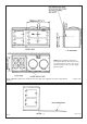
11. Levelling of the simmering plate on the main cooker can be carried out with its top plate
in position and verified across the Module. (See Fig. 8).
12. Complete the main cooker build and loosely screw down the top plate.
13. Apply tape (provided) to the underside of the lap strip on the Module top plate.
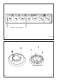
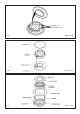
14. Replace module hotplate. Reassemble in reverse order (See section 4). Ensure burner
heads and burner caps are correctly located (See Fig. 9A, 9B and 9C), and electrodes
are not damaged.
15. Replace Module top plate as follows:-
a) Support top plate at front and reconnect the wiring to the two neons.
b) Carefully lower the top plate into position taking care not to damage wiring or neons.
c) Ensure holes for control spindles are aligned correctly, and replace 2 screws into
control panel.
d) Loosely screw the top plate down with 4 retaining screws.
16. Verify that the two top plates are level.
17. Secure handrails as shown on Instruction Sheet EINS 511080.
18 Finally tighten both top plates.
Commission the main AGA cooker, as stated in the relevant Installation Instructions and carry
out functional tests on each of the features on the Module. (See Users Instructions).
11