
Technical data
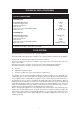
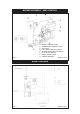
SEE FIG. 2
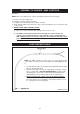
NOTE: Prior to assembly remove controls mounting bracket from burner housing.
1. Fit gas cock to inlet supply pipe.
2. Fit burner assembly to burner housing.
3. Fix AIMS control mounting bracket to burner housing.
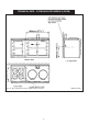
4. Attach wiring to AIMS control board (See Fig. 3) and solenoid plugs onto solenoids. Fix wires
to cable clamp.
5. WHEN FITTING
AIMS CONTROL COVER:
(a) Take care to route solenoid cables through notch at rear of cover.
(b) The AIMS control knob must pass freely through the clearance hole in the
controls cover. Avoid distorting the control spindle, as this could damage the
PCB. (NOTE: It may be necessary to adjust the fit of the burner housing to front
plate, to fit controls cover correctly).
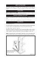
ASSEMBLY OF BURNER - AIMS CONTROLS
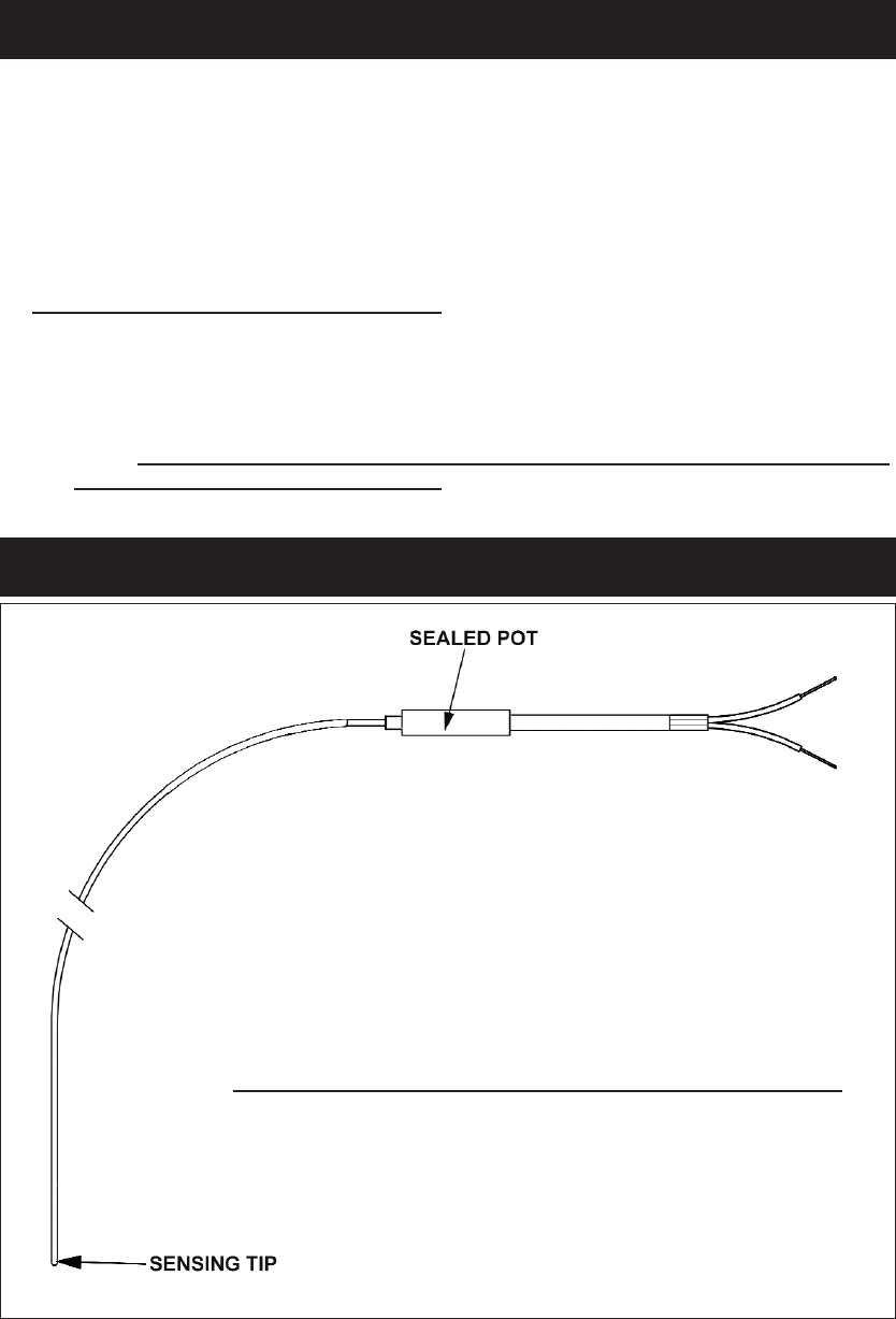
OVEN THERMOCOUPLE
Fig. 4 DESN 515277 A
NOTE: On AIMS controlled cookers, there is an oven thermocouple
sensor, which is connected to the control PCB (See Wiring Diagram, Fig.
3).
1. Feed the thermocouple sensor and thermostat phial through the guide
tube into the Roasting Oven.
2. Fit the thermocouple sensor to the support plate so that the sensing
tip is as show in Fig. 5. DO NOT OVERTIGHTEN the clamp as this
may damage the sensor. Also, fit thermostat phial through hole in
clamping bracket. Screw support plate to top of roasting oven.
3. When assembling the controls cover to the burner housing:-
Ensure that the thermocouple sensor goes through the notch in the
top of the controls cover, and that the sealed pot is inside the cover
(i.e. sealed pot must not be trapped).
10