
Installation Guide
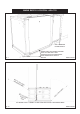
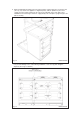
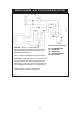


2. Position the plinth alongside the AGA Total Control leaving no gap between the two plinths
(See Fig. 8).
Check with a spirit level that the plinth level is correct, and also check height differential
between the hotcupboard plinth and Total Control plinth is correct
7
/16” (11mm). If necessary,
use shims in each corner to level the plinth.
Fig. 8 DESN 516564
HOTCUPBOARD
PLINTH BASE
7
/16” (11mm) HEIGHT
DIFFERENTIAL
+1
- 0
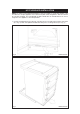
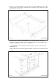
3. Attach hotcupboard plinth to the AGA Total Control plinth using M6 screws and washers
provided (See Fig. 9).
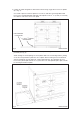
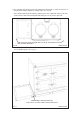
Attach locking screw and jacking screw into plinth. Make sure at this stage that the jacking
screw does not protrude beyond outer face of plinth. Ensure locking screw is located into
AGA TC3 plinth but not fully tightened. A gap of approximately 3mm should be present
between the plinths apart from at the very front where the hotcupboard spacer plate should
be touching the AGA TC3 plinth,
Fig. 9 DESN 516550
13