OPERATOR’S MANUAL Welcome to the world of precision, hands-free steering 2012-09 PN 602-0295-01 REV B
Important Information Refer to your hardware installation manual for complete installation requirements before operating the GeoSteer system. Trademark All brands and products names, unless otherwise stated, are registered trademarks of Novariant, Inc. Technical Support Contact your dealer for technical support.
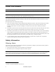
LEGAL DISCLAIMER Note: Read and follow ALL instructions in this manual carefully before installing or operating the GeoSteer1 system. Note: Take careful note of the safety information in the Safety Information section of this manual and the additional safety messages provided throughout this and any other supplemental manuals provided. The manufacturer disclaims any liability for damage or injury that results from the failure to follow the instructions, cautions, and warnings set forth herein.
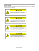
To understand the potential hazards associated with the operation of a GeoSteer equipped vehicle, read the provided documentation prior to installing or operating the GeoSteer system on a vehicle. To prevent accidental death or injury from being run over by the vehicle, never leave the vehicle’s operator seat with the GeoSteer system engaged.
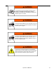
Verify that you are in a stable position on the vehicle’s platform or stairs when installing or removing the GeoDock (the antenna assembly on top of the cab) so you do not fall. If the vehicle does not provide a safe platform, use a ladder to safely access the vehicle’s roof. To avoid electrical shock hazards, remove the GeoDock and/or other antennas from the vehicle before driving under low structures or low electrical power lines.
Caution Alerts The GeoSteer system installer and manufacturer disclaim any responsibility for damage or physical harm caused by the failure to adhere to the following safety requirements: The GeoDock must be removed when transporting or driving the vehicle at speeds above 31 mph (50 km/h). The GeoDock can possibly detach due to wind loads at higher speeds. The GeoSteer system does not detect obstacles in the vehicle’s path.
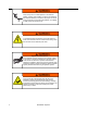
The GeoDock must always be firmly secured to the mounting plate via the magnet whenever the vehicle is in operation to prevent the GeoDock from releasing from its bracket and falling and to ensure the GeoDock is placed at the same point every time. REGULATORY INFORMATION United States FCC Class A Statement – Notice to Users; The GeoSteer system has been tested and found to comply with the limits for a Class A digital device, pursuant to Part 15 of the FCC rules.
Compliance Information The GeoSteer Control unit can contain an internal cellular-modem and can send signals through wireless technology or through an external data communications radio. Table 1-1 lists these components and their related compliance approval numbers.
Table of Contents Chapter 1 System Overview .............................................................................................. 1 Overview.......................................................................................................................................1 GeoSteer System Installation Overview .......................................................................................2 1 Display Kits....................................................................................
Auto Calibrate.............................................................................................................................53 Common Calibration Steps ..................................................................................................54 Compass Calibration.................................................................................................... 55 Wait For Heading ........................................................................................................
Throughput ..........................................................................................................................99 Base Satellites ......................................................................................................................99 Base Location ....................................................................................................................100 Update Base Station Location.............................................................................
Details .......................................................................................................................................141 Feature Code .............................................................................................................................142 Activating a Feature Code .................................................................................................
1 System Overview The System Overview chapter information is provided in the following sections: • • • • • • Overview GeoSteer System Installation Overview Accessing AutoSteer Setup Screens Transferring GeoSteer from Vehicle to Vehicle Changing SIM Card in GeoSteer GeoSteer Control Unit LED Diagnostics Overview The GeoSteer system is a high precision GPS positioning system and vehicle interface controller that provides additional functions and features to the Display.
GeoSteer System Installation Overview GeoSteer System Installation Overview This section provides an overview of what is required to complete a GeoSteer system installation. To aid in clarifying the complete installation, this section also includes the parts and kits that are not included with this vehicle installation kit. A GeoSteer system installation can be broken down into four sub-categories that need to be ordered to complete the installation.
GeoSteer System Installation Overview There are a number of options available for each sub-category. Each of these options comes with their own installation and operational manuals that should be referred to during their part of the installation. 1 Display Kits GeoSteer is compatible with multiple Display options. The Displays are ordered as a separate component and include their own installation and operator’s instructions.
GeoSteer System Installation Overview GeoSteer CDMA This version is used primarily in North America. It has a CDMA modem installed in the GeoSteer control unit that can be used for remote diagnostics and NTRIP correction services. Figure 1-2 GeoSteer CDMA Table 1-1 GeoSteer CDMA Breakdown 4 Item Component Part Number 1. GeoSteer Assembly - CDMA 200-0601-XX 2. Cable, GPS Coax 201-0516-01 3. Kit Documentation 200-0593-03 4. Cable, Cell Modem Coax 201-0539-02 5.
GeoSteer System Installation Overview GeoSteer No Cell This version is used primarily in South America and can be ordered as an option in Australia. There is no cell modem installed inside the GeoSteer control unit. Figure 1-3 GeoSteer Cell Free Table 1-2 GeoSteer Cell Free Breakdown Item Component Part Number 1. GeoSteer Assembly - No Cell 200-0617-XX 2. Cable, GPS Coax 201-0516-01 3. Kit Documentation 200-0593-03 4.
GeoSteer System Installation Overview GeoSteer GSM Europe This version is used primarily in Europe. It has a GSM modem configured to work in the European Union installed in the GeoSteer control unit that can be used for remote diagnostics and NTRIP correction services. The GeoSteer control unit has a SIM card slot that allows the user to easily change SIM cards for a custom data plan if necessary. Figure 1-4 GeoSteer GSM Europe Table 1-3 GeoSteer GSM Europe Breakdown 6 Item Component Part Number 1.
GeoSteer System Installation Overview GeoSteer GSM Australia This version is used primarily in Australia. It has a GSM modem configured to work in Australia installed in the GeoSteer control unit that can be used for remote diagnostics and NTRIP correction services. The GeoSteer control unit has a SIM card slot that allows the user to easily change SIM cards for a custom data plan if necessary. Figure 1-5 GeoSteer GSM Australia Table 1-4 GeoSteer GSM Australia Breakdown Item Component Part Number 1.
GeoSteer System Installation Overview GeoDock Pro The GeoDock Pro is the roof mounted piece of the GeoSteer system that contains the GPS Antenna and Cell Modem antenna. The GeoDock Pro houses the optional GS-900 or GS-450 Radio Modems or the GS-OmniSTAR Demodulator when they are installed. Figure 1-6 GeoDock Pro GeoDock Pro – No Cell This version of GeoDock is the same as the GeoDock Pro except the assembly does not have a Cell Modem Antenna or coax connector installed on it.
Accessing AutoSteer Setup Screens connect the GeoSteer system to the vehicle. Specific instructions for the vehicle installation kits are provided with the installation kits. Refer to those instructions when installing the vehicle kit. Note: The list of supported vehicle-specific kits is always being expanded. Contact your AutoSteer dealer for the latest list of vehicle-specific installation kits to see if the vehicle being installed on has a released kit.
Transferring GeoSteer from Vehicle to Vehicle Figure 1-8 AutoSteer Setup Opening Screen The five folder tabs along the top of the screen separate the GeoSteer configuration and monitoring functions into sub groups to simplify management.
Transferring GeoSteer from Vehicle to Vehicle Removing the GeoSteer System from a Vehicle 1. Locate the GeoDock on the roof of the vehicle. 2. Disconnect the GPS Coax (Blue) by splitting the TNC Connectors shown. 3. If the GeoDock has a Cell Modem Antenna, disconnect the Cell Modem Antenna Coax (Orange) by splitting the TNC Connectors shown. 4. If the GeoDock has an optional GS-900, GS-450, or GS-OmniSTAR Demodulator, disconnect the 12-pin Power/Data Connector shown.
Transferring GeoSteer from Vehicle to Vehicle 7. Locate the GeoSteer Control Unit on the vehicle. 8. Disconnect the GPS Coax (Blue) TNC Connector from the GeoSteer Control Unit. 9. If the GeoDock has a Cell Modem connection, disconnect the Cell Modem (Orange) SMA Connector from the GeoSteer Unit. Figure 1-10 Locate GeoSteer Control Unit on Vehicle TNC GPS Coax (Blue) Connector SMA Cell Modem Coax (Orange) Connector (if equipped 10.
Transferring GeoSteer from Vehicle to Vehicle 12. Remove the four 8-32 x 1/2 Hex Screws using a 1/4 inch nut driver. This releases the GeoSteer Control Unit from the vehicle mounting bracket so it can be moved to another vehicle. Figure 1-12 Remove Screws Holding GeoSteer Control Unit Remove the Four Screws 13. Remove the Display from the cab using the instructions provided in the Display Operator’s Manual. Installing the GeoSteer System on to Vehicle 1.
Transferring GeoSteer from Vehicle to Vehicle 3. Attach the GeoSteer Main Cable Harness connector to the left side connector on the GeoSteer Control Unit. Match the Yellow dots on the harness to the GeoSteer Control Unit Connector. Use a 1/4 inch nut driver to tighten the connector. 4. Attach the Vehicle Specific Cable Harness (if required) to the right side connector on the GeoSteer Control Unit. Match the White dots on the harness to the GeoSteer Control Unit Connector.
Transferring GeoSteer from Vehicle to Vehicle 7. Locate the GeoDock Mounting Plate on top of the cab. Figure 1-16 GeoDock Mounting Plate 8. Attach the GeoDock to the mounting plate taking care to match the mounting tabs on the GeoDock with the tabs on the mounting plate.
Changing SIM Card in GeoSteer 9. Attach the GPS Coax (Blue) TNC Connector to the connector on the GeoDock. 10. If the GeoDock has a Cell Modem Antenna, attach the Cell Modem Antenna Coax (Orange) TNC Connector to the connector on the GeoDock. 11. If the GeoDock has an optional GS-900, GS-450, or GS-OmniSTAR Demodulator, connect the 12-pin Power/Data Connector to the back of the radio modem or demodulator.
Changing SIM Card in GeoSteer 2. Loosen the two screws holding the SIM Card slot cover on with a 2mm Allan wrench supplied with the GeoSteer System and remove the cover. The screws stay attached to the cover. Figure 1-20 Remove Cover by Loosening Screws Remove Screws 3. The edge of the SIM Card will be visible. Gently push the SIM card into the slot and then release. The SIM Card should pop out of the slot.
Changing SIM Card in GeoSteer Note: Never force the SIM Card into the slot. It should slide easily in. If it does not verify that it is orientated correctly. 6. Replace the SIM Card cover to protect it. Tighten the two screws with a 2mm Allan wrench. 7. Power up the GeoSteer system and navigate to the AutoSteer Setup page. Configure the SIM card following the procedure provided in the Configure SIM section on Page 135.
GeoSteer Control Unit LED Diagnostics GeoSteer Control Unit LED Diagnostics The GeoSteer Control Unit has been designed with four LEDs that can be used to help determine the status of the GeoSteer system as well as provide some basic troubleshooting information. Figure 1-22 shows the front panel of the GeoSteer Control Unit. The LEDs will be off, Green, or Amber. Figure 1-22 Front Panel of GeoSteer Control Unit Use Table 1-5 for the definitions of the different LEDs and colors.
2 Vehicle Tab The Vehicle Tab chapter contains information in the following sections: • • • • • • Overview Setup Wizard Manage Vehicle Auto Calibrate Steering Adjust Steering Components Overview Figure 2-1 AutoSteer Setup Vehicle Tab The Vehicle menu enables the user to configure a new vehicle, manage existing vehicles, perform an auto calibration of a vehicle, make steering adjustments and manage steering components.
Setup Wizard • • • • • Setup Wizard – Walks the user through setting up a new vehicle. Manage Vehicle – Allows the user to select, edit, delete, or export/import vehicle profiles into the GeoSteer system. Auto Calibrate – Allows user to start or restart a vehicle calibration for the current vehicle.
Setup Wizard Figure 2-2 WAAS/EGNOS Initial Setup Screen The GeoSteer system can detect and simultaneously track two separate WAAS or EGNOS PRNs. If the Primary PRN becomes unavailable, the system will automatically switch to the Secondary PRN. To change either of the PRNs to a different satellite, press the Change Primary or Change Alternate button. Refer to the WAAS or EGNOS websites to determine satellite availability and health for your location.
Setup Wizard Set RTK Radio Modem Channel or Frequency If the GeoSteer detects a GS-900 or GS-450 Radio Modem, the user will be prompted to enter a channel or frequency to match the channel or frequency of the transmitting Base Station. Press the Change Frequency or Change Channel button to set this value. Figure 2-4 Set RTK Radio Modem Channel or Frequency Use the keypad shown in Figure 2-5 to enter the channel or frequency used on the Base Station.
Setup Wizard Set OmniSTAR Options If the GeoSteer detects an OmniSTAR Demodulator, the user will be prompted to enter a channel to match their location. OmniSTAR has different satellite feeds depending on the GeoSteer system geographic location. Press the Change Channel button to set this value. Figure 2-6 OmniSTAR Setup The OmniSTAR Channel Selection screen will display all the current OmniSTAR channels that are available.
Setup Wizard After the channel and startup accuracy have been selected, press the Blue Right Arrow button shown in Figure 2-6 to continue to the next step. Precision Preference Selection GeoSteer is designed to allow the user flexibility in selecting the accuracy level the system operates at. Depending on the GeoSteer Feature Codes that have been unlocked, the geographic location, OmniSTAR Demodulator that may be installed, the user can choose from Autonomous Pass-to-Pass all the way up to RTK.
Setup Wizard • • • • • • • RTK Only – This mode is only displayed if the RTK Feature Code has been unlocked on the GeoSteer. The system must have a RTK source from a Base Station via a Radio Modem or from a NTRIP source via the Cell Modem. If selected, the GeoSteer assumes the user must be 99.9% sure of position. It requires a RTK link at all times and will disengage AutoSteering if the link is lost. This setting expects good satellite geometry and low PDOP.
Setup Wizard Select Vehicle Type The Vehicle Type represents the type of vehicle the GeoSteer is installed on. The various vehicle types generally have different control parameters and measurement points. This setting allows the system to determine which options will be presented to the user in later steps. Press the Gray Up and Down arrows or directly select the vehicle type.
Setup Wizard Select Vehicle Make The Vehicle Make represents the manufacturer of the vehicle. The vehicle manufacturers that have Vehicle Specific GeoSteer Installation Kits available are shown in this list. Press the Gray Up and Down arrows or directly select the appropriate Vehicle Make from the list. Note: If the vehicle manufacturer is not listed on this screen, select Generic from the list. This allows you to create a vehicle that does not have a factory supported installation kit.
Setup Wizard After Vehicle Model has been selected, press the Blue Right Arrow button to continue to the next step. Select Controller Type The Controller Type represents the controller the GeoSteer will be interfaced with in order to steer the vehicle. GeoSteer can be interfaced with a number of controller options including the standard AutoSteer valves, OnTrac2+, as well as a number of factory installed steering systems.
Setup Wizard Naming the Vehicle The Vehicle Name screen allows the user to enter a custom name for the vehicle. This name is independent of the name provided on the Display side of the vehicle setup. You cannot use the same name twice in GeoSteer system. Use the on screen keyboard to type in the name of the vehicle. Figure 2-14 Vehicle Name Special keys on the keyboard: • • • • • BACK ARROW – This is the delete key. UP ARROW – This is the shift key. Use this to type in capital letters.
Setup Wizard Figure 2-15 Vehicle Wheel Base After the Wheel Base has been entered, press the Blue Right Arrow button to continue to the next step Antenna Fore/Aft The Antenna Fore/Aft measurement is the distance the GeoDock GPS antenna is attached to the vehicle as compared to the Pivot Point of the vehicle. The Pivot Point of the vehicle is the place where the vehicle rotates around as it turns left or right.
Setup Wizard Note: This measurement should be accurate to within 1 inch (2.5 cm). Figure 2-16 Antenna Fore/Aft The GPS antenna can be mounted in front or behind the Pivot Point. Press the button that indicates which side of the Pivot Point the GPS antenna is mounted. If the value is 0.0, it does not matter which button is pressed. • • Fore – This indicates the GPS antenna is located in front of the vehicle’s Pivot Point. Aft – This indicates the GPS antenna is located behind the vehicle’s Pivot Point.
Setup Wizard Figure 2-17 Antenna Lateral Offset For best results, the GeoDock should be mounted along the centerline of the vehicle; however it can be mounted to the left or right of the centerline if necessary. Press the button that indicates which side of the centerline the GPS antenna is mounted. If the offset is 0.0, it does not matter which one is selected. • • Left – This indicates that the GPS is to the left of the centerline. Right – This indicates that the GPS is to the right of the centerline.
Setup Wizard Figure 2-19 Antenna Height After the Antenna Height has been entered, press the Blue Right Arrow button to continue to the next step. GeoSteer Fore/Aft Just like the GPS antenna, the location of the GeoSteer Control Unit must be entered into the system. These measurements are important for GeoSteer to achieve its rated performance. All measurements entered into the GeoSteer system should be measured to the center point of the GeoSteer Control Unit box at the top surface.
Setup Wizard The GeoSteer Fore/Aft measurement is the distance the GeoSteer Control Unit is attached to the vehicle as compared to the Pivot Point of the vehicle. The Pivot Point of the vehicle is the same point that was used to enter the Antenna Fore/Aft. For an explanation of the location of the Pivot Point on the vehicle refer to the Antenna Fore/Aft section on Page 32. First identify the Pivot Point on the vehicle that the GeoSteer is being installed on.
Setup Wizard Note: The units of measure shown in the AutoSteer Setup pages are configured on the Display side and passed to the GeoSteer menus. Refer to your Display Operator’s Manual for instructions on how to set the units of measure. Note: This measurement should be accurate to within 1 inch (2.5 cm). Figure 2-22 GeoSteer Lateral Offset The GeoSteer Control Unit can be mounted to the left or right side of the centerline.
Setup Wizard Figure 2-23 GeoSteer Height After the GeoSteer Height has been entered, press the Green Check button to continue to the next step. GeoSteer Orientation The GeoSteer Control Unit needs to know which orientation it is mounted in or the system will not work properly. If the GeoSteer Control Unit has been installed according to the Vehicle Specific Installation Instructions, the orientation will already be shown on the GeoSteer GCU Orientation screen as shown in Figure 2-24.
Setup Wizard • Enter Angles – Use this button if the GeoSteer Control Unit is not in the orientation shown and it is not mounted orthogonally. This is only used when custom angles must be entered. Contact your AutoSteer Dealer for assistance in entering the correct angles. For more information on how to use the Get Orientation and Enter Angles screens for entering custom orientations of the GeoSteer Control Unit, refer to one of the corresponding sub-sections.
Setup Wizard Figure 2-26 GeoSteer Warning Press the Green Check button only if the angles have been provided by your AutoSteer Dealership. If the angles are not known, press the Red X button. Once the Warning screen has been accepted, the GeoSteer expects the user to enter custom angles to tell the system how the GeoSteer Control Unit is mounted on the vehicle. These angles must be accurate. There are three angles that need to be entered.
Setup Wizard Figure 2-28 Base Orientation Position with (X=0, Y=0, Z=0) Notice GeoSteer Control Unit Orientation as Compared to Vehicle Orientation Adjust the angles for X, Y, and Z so that they tell the GeoSteer system how many degrees it must be rotated from the Base Orientation Position shown in Figure 2-28 to match the actual orientation on the vehicle. This process should only performed by someone that has had the proper training. Contact your AutoSteer dealer for support.
Setup Wizard Manual Steering Override If the installation has a pressure transducer installed on the vehicle or the GeoSteer is connected to an OnTrac2+ or other mechanical steering device, the Setup Wizard will automatically take the user to the Manual Steering Override screen so that it can be calibrated prior to beginning the Auto Calibrate procedure. Depending on the installation, refer to the proper sub-section below.
Setup Wizard Once the Manual Steering Override setting has been set, press the Blue Right Arrow button to continue to the next step. The Setup Wizard will automatically start the Auto Calibrate procedure. Refer to the Auto Calibrate section on Page 53 for more information on these steps. Autocal Figure 2-31 Manual Steering Override Auto Calibrate Wizard The Manual Steering Override Auto Calibrate wizard automatically calibrates the manual steering override value.
Setup Wizard Continue driving and then press the Start button. The vehicle will first appear to do nothing and then later the steering axle will make a series of quick left and right small turns. Once the auto calibration has completed, the Save Calibration screen will appear. Figure 2-33 Save Calibration Press the Green Check button to save the calibration and continue to the next step. The Setup Wizard will automatically start the Auto Calibrate procedure.
Manage Vehicle The following information and controls are available on the Manual Steering Override screen for Mechanical Steering Devices: • • • • • • Current Graph – This graph shows a graphically representation of the current reading which is the shaded green area starting from the left side of the graph. The kick out current is shown on the graph by the triangles on the bottom and top of the graph. Saved – This is the current value that is currently saved as the kick out current.
Manage Vehicle stored on the GeoSteer is displayed below the Active Vehicle. If the GeoSteer is moved to a different vehicle, the user must activate the new vehicle on the GeoSteer. To select a new vehicle, first use the Up/Down Arrows or directly select the vehicle from the list and highlight it. Next press the Select button. This will change the vehicle that is displayed in the Active Vehicle box to the one that was highlighted and reprogram the GeoSteer Control Unit to control that vehicle.
Manage Vehicle To edit a vehicle, first use the Up/Down Arrows or directly select the vehicle from the list and highlight it. Next press the Edit button. This will take the user through the Edit Vehicle wizard. Instead of repeating all the information for the Edit Vehicle screens in this section, please refer back to the Create Vehicle section for specific information on how to measure and enter the proper information for each configuration option.
Manage Vehicle Figure 2-39 Confirm Delete Vehicle Press the Green Check button to delete the vehicle and return to the Manage Vehicle screen. Press the Red X button to cancel deleting the vehicle and return to the Manage Vehicle screen. Export/Import Vehicles The Export/Import button allows the user to import or export vehicle profiles to or from a USB storage device to or from other GeoSteer systems. Users may have more than one GeoSteer system and multiple vehicles they work on.
Manage Vehicle Figure 2-40 Export/Import Manage Management Screen The Export/Import Management window gives the user the following options: • • • Blue Back Arrow – Pressing this button returns the user to the Manage Vehicles screen. Export to Display USB – Pressing this button will start the process of exporting the selected vehicle profile to the USB on the Display.
Manage Vehicle 5. Once the file is ready for export, the Export Vehicle to Display screen will appear. Press the Export button to export the file. Figure 2-42 Export to USB 6. The export process will begin. The screen will count down the time it will take to complete. Figure 2-43 Export Status Bar 7. Once the export is complete, press the Green Check button to return to the Export Vehicle to Display screen. 8.
Manage Vehicle 1. Insert a USB disk with the vehicle profiles to be imported into the USB drive on the Display. 2. Press the Import from Display USB button. 3. The Select a vehicle database file screen will display. Press the Choose File button to select the file to be imported. Figure 2-44 Select Import File 4. The files stored on Display USB drive will show. Select vehicle file to import from the list and then press the Green Check button to start the import.
Manage Vehicle 5. Press the Import button, which is now blue. Figure 2-46 Importing Profiles from USB 6. Wait for the import to complete. Figure 2-47 Wait for Import to Complete 7. The import procedure is complete. Press the Green Check button to return to the Manage Vehicles screen.
Auto Calibrate Auto Calibrate The Auto Calibrate wizard guides the user through the calibration process for the active vehicle. The calibration steps teach the GeoSteer system the characteristics of the vehicle and the steps are critical to achieve optimal control performance. The Auto Calibration process can be Paused and Resumed at any point during the process. Note: The Auto Calibrate wizard takes a significant amount of space for your vehicle to operate within.
Auto Calibrate Figure 2-50 Auto Calibrate Initial Screen (Mechanical Steering Unit / OnTrac2+) Figure 2-51 Auto Calibrate Initial Screen (CAN Bus / ISO) Note: All of the steps of the routine must be completed and the changes saved before the GeoSteer will allow the system to AutoSteer the vehicle. Common Calibration Steps All three Auto Calibrate wizard processes will start with the same Common Calibration Steps. They are as follows: • • • • Compass Calibration – Calibrates the electronic compass.
Auto Calibrate Compass Calibration The GeoSteer Control Unit has a built in compass that allows it to determine the heading the vehicle is facing. The compass needs to be calibrated against the heading calculated by the GPS system. For this step the operator must drive the vehicle in a slow circle to allow the GeoSteer to compare compass readings with the GPS heading. To successfully calibrate the compass, start driving the vehicle 0.5 to 2 mph (0.8 to 3.2 k/h).
Auto Calibrate Figure 2-53 Waiting for Heading Start driving in a straight line at 5 mph (8 k/h). Observe the red needle and green shaded area. Both should line up within a few seconds. If they both line up, press the Next button to continue. Note: If the red needle and the green shaded area do not line up after the compass calibration, verify that the GeoSteer Control Unit has been set to the correct orientation.
Auto Calibrate To start the Tilt Zero Initial Direction calibration, drive the vehicle onto a flat surface and put in park or set the park brake. Press the Resume button and wait for the system to finish the step. When this step is complete, the calibration process will automatically move on to the next step. Tilt Zero Opposite Direction This is the second stage of this calibration procedure.
Auto Calibrate Valve Deadband Oil flow is proportional to voltage or pulse width signal changes sent from the GeoSteer Control Unit. It takes a certain minimum amount of signal to start oil flow through the valve. If the signal is below that minimum amount no oil flows and the steering axle will not move. The range of voltages or pulse widths where there is no valve movement is called the Deadband.
Auto Calibrate The Angle Sensor calibration should start automatically once the Valve Deadband has been determined. If it does not, press the Resume button to start the calibration process. The steering axle will make a hard turn to one direction and then back to the opposite direction to find the maximum Angle Sensor stops. The system will then reposition the Angle Sensor at regularly spaced increments between the two maximum positions and measure the change of heading at each position.
Auto Calibrate Once the Valve calibration process has completed, the Save Calibration screen will appear. Press the Green Check button to accept and save calibration. Press the Red X button to discard all changes. Note: If the Red X is pressed, the calibration will have to be restarted from the beginning. Mechanical Steering Unit / OnTrac2+ This vehicle type uses a mechanical device attached to the steering wheel to control the direction the vehicle steers.
Auto Calibrate Figure 2-61 OnTrac2 Minimum Output Right Calibrating Observe the steering wheel as the vehicle drives forward. When the steering wheel moves 1/4 turn to the right press the Moving! button. Take note of the Right cmd value at the time the Moving! button was pressed in case it needs to be adjusted later. The calibration process will automatically move on to the next step.
Auto Calibrate Observe the steering wheel as the vehicle drives forward. When the steering wheel moves 1/4 turn to the left press the Moving! button. Take note of the Left cmd value at the time the Moving! button was pressed in case it needs to be adjusted later. When this step is complete, the calibration procedure is complete. Save Calibration Figure 2-64 Save Calibration Once the OnTrac2 Minimum Output calibration process has completed, the Save Calibration screen will appear.
Auto Calibrate Note: Some CAN Bus / ISO Controlled vehicles require the user to use the vehicle’s factory supplied engage switch to start the calibration process. If this is require, the calibration screen will notify the user to use that device instead of pressing Resume on the screen.
Auto Calibrate Note: Before the calibration process was started, the Antenna Lateral Offset value should be as close to 0 as possible. If the value is off by more than 4.0 inches (10.2 cm), the calibration process will have to be redone after changing this value. 1. Set an AB line, engage the AutoSteering, and let the vehicle AutoSteer for at least 100.0 feet (30.5 m). 2. Stop the vehicle, place it in park, and disengage the GeoSteer system. 3.
Steering Adjust Steering Adjust After the vehicle has been calibrated, it should perform adequately for most normal field operations. However in some situations, it may be necessary to adjust the steering performance to take into account field conditions, implement selection, traveling speed, etc. The Steering Adjust screen enables the user to adjust the vehicle steering performance to match these changing conditions. You can change the response of the selected item by using the slider bar.
Steering Components ECU Figure 2-69 Steering Components The internal Electronic Control Unit (ECU) connects GeoSteer Control Unit to all the sensors and actuators on the vehicle. The ECU receives information from all the sensors such as the Angle Sensor, pressure transducer, steering encoder, etc. and sends electrical signals to the hydraulic valve. The ECU screen provides the following information: • • • • • Firmware Version – The version of software that is loaded on the ECU.
Steering Components Figure 2-71 Manual Steering Override (Mechanical Steering Device) The Manual Steering Override screens allow the user to adjust the amount of manual steering force required before the AutoSteer system will disengage. This screen is displayed for setting the pressure transducer on Steering Valve type installs and for setting the maximum current on Mechanical Steering Devices.
Steering Components • • Raw Counts – This is the reading that is sent from the Wheel Angle Sensor. This value should increase and decrease smoothly as the steering wheel is turned left and right. If it does not move there is a problem with the Wheel Angle Sensor communications and this will need to be solved before the system can AutoSteer. Zero Curvature – Pressing this button will start a Wheel Angle Sensor test procedure to see if the calibration information is still valid.
Steering Components Figure 2-75 Zero Curvature Test is Bad If the Zero Curvature test passes, the Wheel Angle Sensor is working properly. If the test fails there is most likely a problem with the Wheel Angle Sensor. This can occur if the Wheel Angle Sensor or linkage has been damaged since the original calibration, improper Wheel Angle Sensor installations, or conditions for the test were not favorable (ex. bumpy ground, bad GPS, etc.). Try running the test again.
Steering Components Note: Before performing this test, ensure people and objects are clear of the vehicle. When pressing the Steering Command buttons, the wheels move quickly from side to side. Press the STOP button to halt the wheel movement. Note: For the Hydraulic Valve screen, the Steering Command buttons control the rate at which the steering axle turns. When a button is pressed, the steering axle will turn at a constant rate until the steering axle reaches the stop.
Steering Components The ECU Sensors screen provides the user the raw data that the ECU is measuring. The ECU has a three axes Accelerometer, three axes Gyro, and three axes Compass. These sensors allow the GeoSteer Control Unit to determine the Heading, Roll, and Pitch of the unit. CAN If the GeoSteer system is installed on a vehicle that is interfaced via the CAN Bus or ISO Connection, the CAN screen will display in the Steering Components screens.
Steering Components Figure 2-80 Actuator Read the WARNING message and press the Continue button when all bystanders are away from the vehicle. Figure 2-81 Hydraulic Valve Control Screen Note: Before performing this test, ensure people and objects are clear of the vehicle. When pressing the Steering Command buttons, the wheels or vehicle will move quickly from side to side. Press the STOP button to halt the vehicle movement.
Steering Components Note: Track vehicles will not turn the steering axle, they will start turning at a constant curvature of the command that has been given them. The following are the controls available on the Actuator screen: • • • • • • • • Hard Left – Pressing this button turns the steering axle to the 100% left position and holds it there. xx% Left – The xx represents the Steering Left/Right Percentage that the slider bar has been set to.
Steering Components Figure 2-83 OnTrac2 ECU The OnTrac2 ECU screen provides the following information: • • • • • • • • Firmware Version – The version of software that is loaded on the ECU. Bootloader Version – This is the version of software that is loaded on the ECU to allow it to boot up. Serial Number – This is the Serial Number of the ECU. ECU Type – This provides the type of ECU that is used. Yaw, Roll, and Pitch – These are the raw measurements provided by the ECU.
Steering Components The following are the controls available on the Actuator screen: • • • • • • • • Hard Left – Pressing this button tells the MDU to turn to the right at 100% speed. xx% Left – The xx represents the Steering Left/Right Percentage that the slider bar has been set to. Pressing this button will turn the MDU to the right at xx% speed. 0% – The MDU will not rotate. % Right – The xx represents the Steering Left/Right Percentage that the slider bar has been set to.
3 System Tab The System Tab chapter contains information in the following sections: • • • • • • Overview System Health Manage Settings Accessories Technician Software Upgrade Overview Figure 3-1 AutoSteer Setup System Tab The System menu enables the user to manage system level items. This includes providing an overview of the system health, manage system wide settings, manage accessories that may be connected to the system and upgrading to new software.
System Health Each of the following menu options are explained in detail in this chapter. • • • • • System Health – This provides an overview of the system and displays any issues that may be present. Manage Settings – This allows the user to manage log files, databases, or reset the system back to factory defaults. Accessories – This allows the user to manage any accessories connected to the GeoSteer. Technician – This area is reserved for Service Technicians only.
Manage Settings Figure 3-3 System Health Hardware Example Figure 3-3 shows an example of one of the System Health screens. Each item in the group shows a specific item that is being monitored, a code that explains the status, and a quick reference status symbol that quickly alerts the user to good, bad, or possible problems. Additional items can be scrolled to in some screen by using the Gray Up/Down Arrows at the bottom of the screen.
Manage Settings be sent to your AutoSteer dealer where they can get it analyzed. Most problems can be reproduced and solutions tested using the data that is sent in. If necessary, software patches can be generated by the manufacturer to quickly resolve issues that occur in the field. There are two choices in the Log Files section. • • Copy to Display USB – This copies data to the USB Drive on the Display. Delete – This deletes all log files stored on the system.
Manage Settings Figure 3-6 4. Log File Deletion Warning When the log files have been deleted, a confirmation screen will appear. Press the Blue Check to accept it Figure 3-7 Log Files have been Deleted Note: It may take a few seconds to delete the log files. Let it run for a minute and if it has not finished by then, press the Previous Menu Arrow in the upper, left corner of the screen to end it.
Manage Settings The GeoSteer system stores all the system configurations, vehicle profiles, and historical data, and other information in a database on the internal memory. This database can be exported, saved, and used to restore back onto a system later if necessary. The database also contains a lot of information that can be used by your AutoSteer dealer to help in troubleshooting. There are two choices in the Database section.
Manage Settings Note: The database that is restored onto the unit should come from the same serial number and version of the unit being restored on. Do not backup one GeoSteer unit and use that database to restore onto a completely different one or restore a database from a unit with a different version. It is possible that this may cause data corruption. 1. Insert the USB drive with the database to be restored into the Display USB drive. 2.
Manage Settings 5. Once the file has been selected, press the Restore button to start the process. Figure 3-12 Database File Ready to Restore 6. The restore will begin. The process will take a couple of minutes. Do not touch the system while the restore is taking place. Figure 3-13 Uploading Restore File 7. The system will notify when the database has been restored. Press the Blue Check to acknowledge it. The restore is complete.
Manage Settings Reset Factory Default Figure 3-15 Reset Factory Default There may be occasions when it is necessary to restore a GeoSteer system back to the Factory Default settings. This could be necessary if the system is transferred to a new owner, or the database becomes corrupted on the unit. If this becomes necessary, the user can simply use the Reset Factory Default feature. There is only one choice in the Reset Factory Default section.
Accessories 3. The system will notify when the system has been restored. Press the Blue Check to acknowledge it. The reset is complete. Figure 3-17 Factory Reset Complete Accessories Figure 3-18 Accessories Disabled GeoSteer was designed to allow additional accessories to be developed and attached to it over time if new ones arise. The Accessories menu is used to manage these optional attachments. Currently there is only one accessory available for GeoSteer.
Technician Enable (Disable) To Enable or Disable the Remote Switch, follow the instructions below: 1. From the System tab, press the Accessories button, highlight Remote Switch from the list on the left, and then press the Enable (Disable) button. 2. Once the Enable (Disable) button has been pressed, the button will change to the opposite of what it was and the Current Status will be updated. Figure 3-19 Remote Switch Enabled Technician The Technician screen is password protected.
Software Upgrade Software Upgrade Figure 3-21 Software Upgrade The Software Upgrade screen enables the user to upgrade the system to new versions as new application software bundles are released. Because new software bundles include fixes to known issues, it is recommended users upgrade their system to the latest software release when: • • They experience issues that are known to be fixed on the new software release. Need features which are only available with an upgrade to the latest software.
Software Upgrade 7. Press the Upgrade button to begin the upgrade. Figure 3-23 Start the Upgrade 8. The system will begin the upload of the upgrade file to the GeoSteer. This process will last a minute or two. Figure 3-24 Uploading New Software to GeoSteer 9. The system will then go through the upgrade process and show the progress of the upgrade on the screen. This process can take 10 to 15 minutes.
Software Upgrade 10. When the upgrade is complete, the GeoSteer Control Unit will reboot and then the Upgrade complete screen will display. Press the Blue Check to acknowledge. The upgrade is complete.
4 GPS Tab The GPS Tab chapter contains information in the following sections: • • • • • • • • • Overview RTK OmniSTAR WAAS/EGNOS Precision Settings NTRIP Planning Tool GPS Diagnostics NMEA Out Overview Figure 4-1 AutoSteer Setup GPS Tab Note: Not all the buttons will always be available in the GPS screen. The GPS screen will only allow user to access items that have been unlocked with a Feature Code that has been purchased or if it detects a device that is supported.
RTK To access the GPS menu, refer to your Display Operator’s Manual for instructions on accessing the AutoSteer Setup screens. Once there, press the GPS tab. Each of the following menu options are explained in detail in this chapter. • • • • • • • • RTK – Enables the user to set all the settings related to RTK. OmniSTAR – Enables user to view information about their OmniSTAR subscription and configure the OmniSTAR settings. WAAS/EGNOS – Enables user to configure the WAAS/EGNOS settings.
RTK General Figure 4-2 RTK Settings The General screen displays an overview of the important RTK status info such as: • • • • • • Current Channel – This is the radio channel or frequency that the connected GS-900 or GS-450 is set to. Radio Type – This shows which type of radio is being used.
RTK Figure 4-3 Base Dealer ID # not Activated RTK Connection Type Figure 4-4 RTK Connection Type The RTK Connection Type screen displays the current source of the RTK correction data. This enables the user to select and change the RTK connection type if they have multiple sources available to them. RTK Connection Types available are: • • • Novariant supplied Radio – GS-900/GS-450 – RTK corrections received are via a GS-900 or GS-450 radio kit installed in the GeoDock and supplied by Novariant.
RTK Channel Figure 4-5 Changing Radio Channel The GS-900 radio modem used with the GeoSteer system provides a data link to supply RTK corrections from a Base Station to produce repeatable sub-inch accuracy. The radio modem must be configured to the same channel as is used on the Base Station in order to communicate properly.
RTK Change Channel 1. Press the Change Channel button. 2. Manually enter a new Channel number using the numeric keypad. 3. Press the Green Check button to save the new channel setting or press the Red X to cancel. Figure 4-6 Entering RTK Radio Channel Use Previous 1. Press the Use Previous button. 2. Use the Gray Up/Down Arrow or directly select one of the previously used radio channels. 3. Press the Green Check button to save the new channel setting or press the Red X to cancel.
RTK Frequency Figure 4-8 Changing Radio Frequency The GS-450 radio modem used with the GeoSteer system provides a data link to supply RTK corrections from a Base Station to produce repeatable sub-inch accuracy. The radio modem must be configured to the same frequency as is used on the Base Station in order to communicate properly.
RTK Change Frequency 1. Press the Change Frequency button. 2. Manually enter a new Frequency number using the numeric keypad and select the proper Channel Spacing. Note: The Channel Spacing must be 12.5 kHz or 25 kHz. This must match the channel spacing on the Base Station radio modem. 3. Press the Green Check button to save the new frequency setting or press the Red X to cancel. Figure 4-9 Entering RTK Radio Frequency Use Previous 1. Press the Use Previous button. 2.
RTK Throughput Figure 4-11 RTK Correction Throughput The Throughput screen displays the Current Channel or Current Frequency that the Radio Modem is programmed to. It also shows a graph with the percentage of radio packet data that is received by the GeoSteer. If an obstacle blocks the signal from the Base Station or the radio link is lost for short times, this graph will show this by the percentage dropping down. The graph shows the past 60 seconds of activity.
RTK • • • Elevation – This is the angle the GPS satellite is above the horizon (Higher is higher in the sky). L1 (Pink) –This is the Signal to Noise Ratio for the L1 Band (Higher is better). L2 (Red) –This is the Signal to Noise Ration for the L2 Band (Higher is better). Base Location Figure 4-13 Base Station Location The Base Station Location screen displays information about the Base Station that the GeoSteer is referencing.
RTK The following information is displayed on the Base Station Location screen: • • • • • Saved Location – This is the location of the Base Station that the GeoSteer has stored in its internal database. If the information was stored from a surveyed Base Station, this information will be the same as the location currently transmitted by the Base Station.
RTK Using the Update Saved Location Procedure 1. Power on the Base Station at the job location. Allow the Base Station to run and surveyed in (this can take 24 hours or longer to complete). 2. Power on the Rover. An Initial (and inaccurate) position is displayed in the Saved Location field. 3. Begin work on the part of your job that does not require accurate latitude/longitude or repeatability. 4. After the Base Station has completed a 24 hour survey, navigate from the GPS tab.
OmniSTAR OmniSTAR Note: The OmniSTAR button is only active if the GeoSteer system detects an OmniSTAR Demodulator installed on the GeoDock. OmniSTAR is a wide-area differential GPS service, using satellite broadcast techniques. OmniSTAR offers GPS correction services that improve the accuracy of a GPS receiver. The OmniSTAR services include dual frequency (L1/L2) carrier phase solutions. The accuracy depends on satellite geometry, local conditions, receiver capability, and other variables.
OmniSTAR General Figure 4-16 OmniSTAR Options The General screen enables the user to view information about their OmniSTAR subscription. It provides the following information: • • • • Current Channel – This is the channel the OmniSTAR Demodulator is currently configured to listen to. Serial Number – This is the serial number of the OmniSTAR Demodulator. This is required to be given to OmniSTAR to set up the subscription. End of Subscription – This is the date the current subscription will end.
OmniSTAR Table 4-1 Expected Initial Startup Accuracies for Different OmniSTAR Modes Correction Level Fast Startup High Accuracy OmniSTAR XP 40.0 inches (101.6 cm) 9.0 inches (22.9 cm) OmniSTAR HP 40.0 inches (101.6 cm) 6.0 inches (15.2 cm) Note: If Fast Startup is selected, this only affects the accuracy at the initial startup. The accuracy improves to the highest accuracy enabled by your current subscription in the background as the system continues to run.
WAAS/EGNOS 3. From the GPS screen, press the OmniSTAR button and then select Channel from the list on the right. 4. Press the Change Channel button. 5. Use the Gray Up/Down Arrow button or directly select the channel provided by OmniSTAR to use in your region. Figure 4-19 OmniSTAR Regions 6.
WAAS/EGNOS PRN Figure 4-20 WAAS/EGNOS Setup The PRN screen provides information about the WAAS/EGNOS satellites that are to be tracked. The GeoSteer system can simultaneously track two separate WAAS/EGNOS PRNs. If the Primary PRN becomes unavailable, the system will automatically switch to the Secondary PRN. The PRN screen provides the following information: • • Primary PRN – This is the PRN that is tracked first. Alternative PRN – This is the PRN that is tracked if the Primary PRN is lost.
Precision Settings Change Alternate To set the Alternate PRN follow, the instructions below: 1. From the GPS screen, press the WAAS or EGNOS button and then select PRN from the list on the right. 2. Press the Change Alternate button. 3. Use the keypad to enter the Primary PRN number. 4. After the channel has been set press the Green Check button to save the setting or press the Red X button to cancel. Note: PRNs are satellite identifiers.
Precision Settings Figure 4-23 Precision Settings The Precision Settings screen shows which mode is active at the top of the screen. Changing Precision Mode Each of the selections has specific accuracy levels and operational requirements. An explanation of each setting is provided below: Note: “Flex” is a term that denotes the system switching from one accuracy level to another when a correction source is lost.
NTRIP • • • OmniSTAR Flex to WAAS/EGNOS/Autonomous Mode – This mode is displayed only if the GeoSteer detects that an OmniSTAR Demodulator has been installed on the GeoDock. If the system is running in OmniSTAR mode, the user has the option to “Flex” back to WAAS, EGNOS, or Autonomous Mode if the OmniSTAR signal is lost for some reason. The mode the system will “Flex” to will depend on which region the GeoSteer is located. WAAS and EGNOIS are available in North America and Europe respectively.
NTRIP General (Original Screen) Figure 4-24 NTRIP General The General option displays the status of the NTRIP connection. The General screen provides the following information: • • • Current Status – The lets the user know if the system is connected to the NTRIP stream or not. Server – This is the Server that the system is configured to connect to. Stream – This is the Stream that the system is configured to connect to.
NTRIP Add To add a new profile follow, the procedure below: Note: Prior to adding a new Profile, NTRIP must be set as the selected RTK Source. Refer to the RTK Connection Type section on Page 94 for information on how to set this. 1. From the GPS menu, press the NTRIP button. 2. Press the Blue Up/Down buttons or directly select Profile from the list on the right. 3. Press the Add button to add a new profile. 4. Press the Edit button in the Server section. Figure 4-26 NTRIP Add Profile 5.
NTRIP Figure 4-27 Enter Server IP 6. Press the Edit button in the Port window. Figure 4-28 NTRIP Add Profile (Server Entered) 7. Type in the Port value and then press the Green Check button to save the value or the Red X to cancel.
NTRIP 8. Press the Blue Right Arrow to move onto the next step. Figure 4-30 Server and Port Entered 9. The GeoSteer will connect to the Internet and attempt to download the available NTRIP Streams from the NTRIP server. It will display them. Use the Gray Up/Down Arrows or directly select the stream to use and then press the Blue Right Arrow to continue to the next step. Figure 4-31 NTRIP Streams to Pick from 10. Press the Edit button in the Username window.
NTRIP Figure 4-32 Enter Username and Password 11. Type in the Username and then press the Green Check button to save the value or press the Red X button to cancel. Note: Information type in is case sensitive, be sure to verify the position of the Shift Key to avoid errors. Figure 4-33 Enter Username 12. Press the Edit button in the Password window.
NTRIP 13. Type in the Password and then press the Green Check button to save the value or press the Red X button to cancel. Note: Information type in is case sensitive, be sure to verify the position of the Shift Key to avoid errors. Figure 4-35 Enter Password 14. Press the Blue Right Arrow to continue to the next step.
NTRIP 15. The system will now attempt to connect to the stream. If it is successful, the Connection Successful acknowledgement screen will display. Otherwise an error screen will appear stating the connection failed. If this happens double check the values and continue trying again. On the Connection Successful screen press the Green Check button to save the profile or the Red X to not save the profile. Figure 4-37 Successful Connection 16.
NTRIP Connect Once a Profile has been created and stored in the list, they can be selected and connected to. Follow the procedure below to connect to a Profile: 1. From the GPS menu, press the NTRIP button. 2. Press the Blue Up/Down buttons or directly select Profile from the list on the right. 3. Select the desired Profile from the list of profiles on the left. 4. Press the Connect button. Figure 4-39 Select Profile 5.
NTRIP Delete It may become necessary to delete a Profile that is no longer used. Follow the procedure below to delete a Profile. 1. From the GPS menu, press the NTRIP button. 2. Press the Blue Up/Down buttons or directly select Profile from the list on the right. 3. Select the Profile to be deleted from the list of profiles on the left. 4. Press the Delete button. Figure 4-41 Select Profile to Delete 5.
NTRIP General (After Profile Created) Figure 4-43 NTRIP General After the profile has been created, the General tab will remember the last profile used. The user can then jump straight to this screen to Connect and Disconnect. Connect Follow the procedure below to Connect to the NTRIP server. 1. From the GPS menu, press the NTRIP button. 2. Press the Blue Up/Down buttons or directly select General from the list on the right. 3. Press the Connect button shown in Figure 4-43.
Planning Tool Planning Tool The Planning Tool screen provides information about the predicted quality of the GPS and expected GPS availability. It enables user to make decisions about farming applications based on GPS availability. The following Planning Tool options are available: • • • General – This provides the location of the vehicle. Sky Plot – This provides a graphical representation of the location of the GPS satellites in the sky.
GPS Diagnostics Satellites in circles are GPS and Satellites in a square box are GLONASS. The numbers on them represent each satellite’s PRN. Note: GLONASS is a satellite Navigation System operated by the Russian Government. It is an alternative and complementary system to the US Global Positioning System. Tracking GLONASS satellites may help maintain a valid position, in challenging environments. GLONASS tracking with GeoSteer requires a Feature Code to unlock it.
GPS Diagnostics General Figure 4-48 GPS Diagnostics General The General screen displays the status of a number of operations parameters are explained below: • • • • • • GPS Mode – The current GPS mode the system is operating in. PDOP – (Positional Dilution of Precision) is a measure of the strength of the satellites scatter.
NMEA Out Individual data for each PRN is provided at the bottom of the screen. Use the Gray Left/Right Arrow buttons to select a PRN. The screen displays the following information: • • • • • Elevation – This is the angle the GPS satellite is above the horizon (Higher is higher in the sky). Base L1 (Pink) –This is the Signal to Noise Ratio for the L1 Band at the Base Station (Higher is better). Base L2 (Red) –This is the Signal to Noise Ration for the L2 Band at the Base Station (Higher is better).
NMEA Out GeoSteer supports the following NMEA message formats: • • • • • • • • GGA VTG GSV GSA GLL ZDA RMC XTE GeoSteer supports the following data rates: • • • • • • Off 0.1 Hz 0.2 Hz 1 Hz 5 Hz 10 Hz Messages Configuration To change the configuration of any of the NMEA Message follow the procedure below: 1. Use the Gray Up/Down Arrow buttons or directly select the NMEA Message that is to be modified. 2. Press the Edit button. 3.
NMEA Out Refer to your 3rd party device to determine what versions should be sent. In most cases the Current Version should be safe to send. The Legacy Version is only used on very old 3rd party devices that were not capable of using RTK generated data. Table 4-2 5.
NMEA Out Port Configuration Note: Changing the Baud Rate for Port A on the NMEA Out screen also changes the Baud Rate for the External Radio input. Port A can be used simultaneously for the External Radio In and NMEA Out, however both functions must use the same Baud Rate. To change the Port Configuration, follow the procedure below: 1. Press the Change Baud Rate button. 2. If adjusting Port A, a Warning message will appear. Press the Green Check button to accept it or the Red X button to cancel.
5 Connections Tab The Connections Tab chapter contains information in the following sections: • • • • • Overview Cell Modem (North America CDMA) Cell Modem Default SIM Card (Australia and Europe GSM) Cell Modem Custom SIM Card (Australia and Europe GSM) External Radio Overview Figure 5-1 AutoSteer Setup Connections Tab Note: Not all the buttons will always be available in the Connections screen. If the GeoSteer does not have a built in Cell Modem, the Cell Modem button will not be available.
Cell Modem (North America CDMA) Each of the following menu options are explained in detail in this chapter: • • Cell Modem – This enables user to view information about the cell modem connection and manage various configuration settings. External Radio – This enables the user to configure Port A to communicate with an external 3rd party device.
Cell Modem (North America CDMA) Manage PRL Figure 5-3 Manage Preferred Roaming List (PRL) Preferred Roaming Lists (PRL) are the lists that provide the GeoSteer the order in which they connect to cell phone providers. There are multiple PRLs available so that the GeoSteer can be configured for locations that doe not work as well with the default list. If cell connections are difficult to maintain with one PRL, the user can attempt to use a different PRL that may work better in their area.
Cell Modem Default SIM Card (Australia and Europe GSM) Cell Modem Default SIM Card (Australia and Europe GSM) The Cell Modem screen allows the user to view basic information about the cell modem and network properties. To access the Cell Modem screen, from the Connections menu press the Cell Modem button. Figure 5-5 Cell Modem The Cell Modem screen displays the following information: • • • • Status – This is the status of the modem.
Cell Modem Default SIM Card (Australia and Europe GSM) 1. From the Connections screen, press the Cell Modem button. 2. Press the Change Carrier button. 3. A Roaming Charge Warning screen will appear. If you accept the risks, press the Green Check button otherwise press the Red X button to cancel. Figure 5-6 4. Roaming Charge Warning Screen The system will take a few moments to detect the various Carriers that are available. Once it has found them, it will display them.
Cell Modem Custom SIM Card (Australia and Europe GSM) Advanced Debug The Advanced Debug screen displays information to help your dealer or authorized technician troubleshoot Cell Modem connection issues. To view or save Advanced Debug information: 1. From the Connections screen, press the Cell Modem button. 2. Press the Advanced Debug button. Figure 5-8 Cell Modem Advanced Debug 3. Pass the information provided on this screen to your service provider. 4.
Cell Modem Custom SIM Card (Australia and Europe GSM) The Cell Modem screen displays the following information: • • • • • • Status – This is the status of the modem. It will be Connected, Disconnected, or Connecting. With a customer supplied SIM card, the system will be disconnected unless told to connect by the user. Signal Strength – The Signal Strength will not show a value while the modem is connected.
Cell Modem Custom SIM Card (Australia and Europe GSM) 4. Enter the Access Point information provided by your SIM Card supplier and press the Green Check button to accept the entry or the Red X to cancel. Figure 5-11 Enter Access Point 5. Enter the and provided by your SIM Card supplier in the same manner as the information was entered. Note: The Username and Password are not always required and can often be left blank. 6.
External Radio 7. The main Cell Modem screen will now show the Customer Supplied SIM settings that the system is set to. Figure 5-13 Custom SIM Card Configured External Radio The External Radio screen enables user to set the Baud Rate (data transmission rate) for 3rd party device connections. This allows the GeoSteer to receive RTK information from an external source other than the internal Cell Modem or GS-900 and GS-450 Radio Modems.
External Radio Change Baud Rate Note: Changing the Baud Rate for Port A on the External Radio screen also changes the Baud Rate for the NMEA Out output. Port A can be used simultaneously for the External Radio In and NMEA Out, however both functions must use the same Baud Rate. To change the configuration of Port Configuration, follow the procedure below: 1. From the Connections screen, press the External Radio button. 2. Press the Change Baud Rate button. 3. A Warning message will appear.
6 My Account Tab The My Account Tab chapter contains information on the following: • • • • Overview Call Support Details Feature Code Overview Figure 6-1 AutoSteer Setup My Account Tab Note: In some locations where Remote Services are not available the Call Support will not be available in the My Account screen. The My Account menu enables user to initiate remote technical support, configure and monitor their account parameters.
Call Support (If Available) Note: The Call Support service is only available to users that subscribe to the service plan. Your AutoSteer Dealer CANNOT guarantee the availability, integrity, or reliability of the cellular network in any area. If technical support is required, the user can use the Call Support feature to have a Support Request message with their contact number sent directly to their service supplier.
Details 4. When the Help request is successful, a Help request transmission successful dialog box appears as shown in. Figure 6-4 5. Call Support Successful Press the Blue Check button to return to the My Account menu. Note: If the support request fails, check the status of the cell modem. Refer to the Connections Tab chapter on Page 129 for more information. It is possible the system is not in a place where a cell connection can be made.
To access the Details screen: 1. From the My Account menu, press the Details button. 2. Use the Blue Up/Down Arrows or directly select the item to view in the Details screen. The information about the selected item will appear. Note: If a device is not present or not working properly, the data for each device will show blanks. Feature Code The Feature Code screen displays all the optional features that can be added to the GeoSteer system. These Feature Codes can be purchased at any time.
Feature Code Activating a Feature Code To activate a new Feature Code follow the procedure below: 1. From the My Account menu press the Feature Code button. 2. Use the Gray Up/Down Arrow buttons or directly select an item you wish to activate. 3. Press the Edit button. 4. Enter the Feature Code and press the Green Check button to accept the Feature Code or press the Red X to cancel. Figure 6-7 5.