GeoSteer Installer Installer’ss Reference Reference This document explains must know differences of GeoSteer as compared to ParaDyme steering systems.
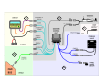
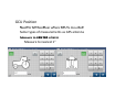
1 2 4 3b 3a
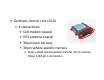
• GeoSteer Control Unit (GCU) • 4 connections: • Cell modem coaxial • GPS antenna coaxial • 30pin main harness • 30pin vehicle specific harness • Color coded (white/yellow) Careful not to reverse these 2 (30 pin) connectors.
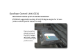
• GeoSteer Control Unit (GCU) – Orientation Orientation must be +/‐ must be +/‐ 3 3⁰ of selected orientation. of selected orientation – STRONGLY suggested mounting GCU at 90 degree angles for all axes. (Unless vehicle specific bracket is used). Items cannot be b placed on top of the GCU. Contact with tools, cables, , , etc will cause poor performance.
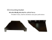
• GCU mounting bracket – Must be firmly M t b fi l attached to vehicle frame. tt h d t hi l f • If bracket it loose, machine vibrations cause poor performance.
• GCU Position –N Need to tell GeoSteer where GCU is mounted d t t ll G St h GCU i t d – Same types of measurements as GPS antenna – Measure to CENTER Measure to CENTER of GCU of GCU • Measure to nearest 1”
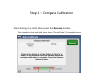
Step 1 – p Compass Calibration p • Start driving in a circle then press the Resume button. – Turn wheels to lock and hold them there. This will take 2‐3 complete turns.
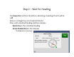
Step 2 – p Wait For Headingg • • • The Green Dot confirms the GCU is calculating a heading (if not it will be red) d) Drive in a straight line at 5.0 mph (8.