
Installation User Manual

Ag Leader Technology
Cable – Keypad, Radar, Switch
Ez-Guide Plus / 500 Installation Instructions
PN: 2005898 Rev A – June 2007 5
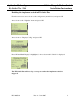
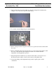
3. If the switch cannot be mounted this way, then the wiring in the switch must be
changed. To do this, first open the switch casing.
4. Loosen the screws holding the green and black wires.
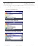
5. Remove the green wire from pin-13 and move it to pin-21 and secure it there with
the screw
6. Remove the black wire from pin-14 and move it to pin-22 and secure it there with
the screw. This will allow the implement switch to be centered when the
implement is in the application position.
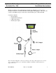
7. Plug the implement switch into any extension cables that you may need to use.
Route the extension cables to the cab and connect to the splitter cable.
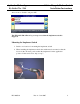
8. Secure the cabling on the implement being careful of pinch points or field
obstructions.