Version 4.
Table of Contents Introduction...............................................................................................................................................................1 Legal Notices.................................................................................................................................................1 Related Information.......................................................................................................................................
Introduction Legal Notices (c) 2009, Trimble Navigation Limited. All rights reserved. Trimble, AgGPS, EZ−Guide, and EZ−Steer are trademarks of Trimble Navigation Limited, registered in the United States and in other countries. Autopilot, Autoseed, FreeForm, OnPath, and SiteNet are trademarks of Trimble Navigation Limited. All other trademarks are the property of their respective owners.
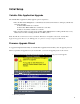
Initial Setup Variable Rate Application Upgrade The Variable Rate Application (VRA) upgrade option is required to: • Allow the EZ−Guide 500 lightbar to communicate and send rate information to third pary variable rate controllers including: ♦ Hardi 5500 variable rate controller ♦ Raven SCS 400 and 600 series variable rate controllers ♦ Rawson Accu−Rate variable rate controller • Allow prescription files to be imported to the EZ−Guide 500 lightbar for sending variable rates to any variable rate controller, i
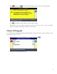
4. Select and then press following screen appears: Press . A screen with an hourglass appears for a few seconds and then the . The lightbar restarts with the new functionality enabled. Note: If the message says "Password upgrade failed. The password entered was not valid.", try entering the password again. If it fails again, contact your local reseller.
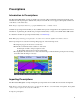
Prescriptions Introduction to Prescriptions The EZ−Guide 500 lightbar can import variable rate prescription files in Shapefile format. The application rate information from the prescription attribute file (.dbf) is sent to EZ−Boom or a supported third party variable rate controllers to control flow rates. Note: All prescription files must use geographic WGS84 for the coordinate system. Variable rate prescription functionality is only available after a password upgrade has been purchased.
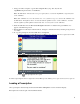
1. Using your office computer, copy the three Shapefile files (.shp, .dbf, .shx) into the \AgGPS\Prescriptions\ folder on a USB drive. Note: The EZ−Guide 500 will only detect prescription files located in the \AgGPS\Prescriptions\ folder on the USB drive. Note: If the USB drive does not already have the correct folders set up, you can insert the USB drive into the EZ−Guide 500 lightbar, turn it on and wait until the lightbar has detected the USB drive, and then turn the lightbar off.
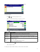
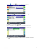
After the field is selected, the Available Prescriptions List screen appears. To load a prescription: 1. Press or to select the prescription to load. Note: To continue without loading a prescription, select None. 2. Press . The Prescription Parameters screen appears. 3. Press to configure the prescription setup: ITEM Rate Column Rate Units Scale Factor Rate Outside Polygon DESCRIPTION Column in the prescription .dbf file containing the rate information.
1. Select the icon and press 2. Select No and then press . The Finished With Field? screen appears. . The Create New or Select Old Swath screen appears. 3. Press to choose Select AB Line and press . 4. Select the current AB Line and press . The Select Stored AB Line screen appears. Note: If there is only one AB Line in the current field, this step is done automatically. 5. Press to keep the current implement setup. The Available Prescriptions List screen appears.
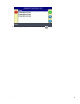
6. Select the prescription file you want to load and press .
EZ−Boom 2010 System Connecting the EZ−Boom 2010 System Connect the EZ−Boom 2010 system to the EZ−Guide 500 lightbar as shown below. ITEM 1 2 3 4 5 6 7 8 DESCRIPTION EZ−Guide 500 lightbar Ag 15 antenna Antenna cable (PN 50449) EZ−Guide 500 power cable (PN 62817) To power EZ−Boom to EZ−Guide 500 cable (PN 61437) EZ−Boom controller CAN terminator (PN 59783) Connect the EZ−Boom 2010 system to the EZ−Steer 500 system as shown below.
ITEM 1 2 3 4 5 6 7 8 DESCRIPTION EZ−Guide 500 lightbar Ag 15 antenna Antenna cable (PN 50449) EZ−Guide 500 power cable (PN 62817) To power EZ−Boom to EZ−Guide 500 cable (PN 61437) EZ−Boom controller EZ−Steer 500 system EZ−Boom Features When the EZ−Boom 2010 system is connected to the lightbar, the following features appear or become available: 10
ITEM DESCRIPTION 1 The actual current rate Note: If the rate switch position is M (Manual) and the vehicle is not moving, NA is displayed. 2 Auto/manual switching indicator shows which switching mode the controller is in. * When the controller is in manual switching mode, the indicator is gray. * When the controller is in automatic switching mode, the indicator is in color. 3 Fence nozzle indicator If a fence nozzle is enabled, an indicator appears.
EZ−Boom Flow Calibration When you perform the EZ−Boom 2010 system flow calibration: 1. Enter the Flow Meter Calibration number: 2. Do one of the following: ♦ If you know that the setting is correct, press the function button to save the calibration number that you entered and exit the menu. The system is now calibrated. ♦ To complete a full calibration: a. Enter the target rate, the speed, and the total number of nozzles. b. Select Calibrate Now and then press . The Flow Calibration screen appears. c.
To manually enter a rate to send to the controller, select Configuration / Application Control / Target Rate . Alternatively, load a prescription so the EZ−Guide 500 lightbar automatically sends target rates to the EZ−Boom 2010 system. For more information, see Prescriptions. Note: The EZ−Boom rate switch must be set to Rate 1 to use target rates from a prescription file. Automatic boom switching The EZ−Guide 500 lightbar will do automatic boom switching for the EZ−Boom 2010 system.
There are two settings, measured in seconds: Valve On Latency − the time that it takes for the system to begin spraying after you turn it on. Valve Off Latency − the time that it takes for the system to stop spraying after you turn it off. Tip: To calculate the latency values, time your system with a stopwatch Allows you to double−spray (buffer) a set distance to ensure complete coverage and avoid skips.
Hardi 5500 Variable Rate Controller Connecting a Hardi 5500 Controller Connect the Hardi 5500 variable rate controller to the EZ−Guide 500 lightbar COM port as shown below. ITEM 1 2 3 4 5 6 7 DESCRIPTION EZ−Guide 500 lightbar Ag15 antenna Antenna cable (PN 50449) EZ−Guide 500 power cable (PN 62817) To power Hardi 5500 (COM1) to EZ−Guide 500 cable (PN 59043) Hardi 5500 Controller Note: The Hardi 5500 controller must have firmware version 3.
Alternatively, connect the Hardi 5500 variable rate controller to the EZ−Guide 500 lightbar AUX port as shown below. ITEM 1 2 3 4 5 6 7 8 9 DESCRIPTION EZ−Guide 500 lightbar Ag15 antenna Antenna cable (PN 50449) EZ−Guide 500 power cable (PN 62817) To power EZ−Guide 500 AUX port cable (PN 62609) Serial port extender (PN 63076) Hardi 5500 (COM1) to EZ−Guide 500 cable (PN 59043) Hardi 5500 Controller Note: The Hardi 5500 controller must have firmware version 3.
TO EZ−GUIDE 500 TO HARDI PINS PINS 2 −−−−−−−−− 3 3 −−−−−−−−− 2 5 −−−−−−−−− 5 Hardi Controller Setup To configure the EZ−Guide 500 lightbar to communicate with the Hardi 5500 variable rate controller, do the following: EZ−Guide 500 lightbar setup On the EZ−Guide 500 lightbar, do the following: 1. Select Configuration / Application Control / Controller Settings . 2. Press . The Controller Settings screen appears. 3. Change Controller type to Hardi 5500.
5. Select Continue and press 6. To configure the number of boom sections and section widths, go to the Application Control / Boom Setup menu. Hardi controller setup On the Hardi 5500 controller, do the following: 1. On the Hardi 5500 controller, go to the Settings menu. 2. Change Remote to Enable . For more information on configuring or calibrating the Hardi 5500 controller, refer to the Hardi instruction manual.
ITEM DESCRIPTION 1 The actual current rate Note: Since the Hardi controller does not report the actual applied rate to the EZ−Guide 500 lightbar, this item will always appear as N/A. 2 Auto/manual switching indicator shows which switching mode the controller is in. * When the controller is in manual switching mode, the indicator is gray. * When the controller is in automatic switching mode, the indicator is in color. 3 Fence nozzle indicator If a fence nozzle is enabled, an indicator appears.
Alternatively, set the User Mode to Advanced and then select Configuration / Application Control. Using the Hardi Controller When using a Hardi variable rate controller with the EZ−Guide 500 lightbar, note the following: Boom setup If the boom setup differs between the EZ−Guide 500 lightbar and the Hardi controller, a warning message appears on the lightbar. You must configure the EZ−Guide 500 lightbar to match the Hardi controller. To do this, select Configuration / Application Control / Boom Setup.
To manually enter a rate to send to the controller, select Configuration / Application Control / Target Rate . Note: When sending a target rate to the Hardi 5500 controller that is higher than 99.9, the value will be rounded to the nearest whole number. For example, 0−99.9 is not rounded. 101.4 is rounded to 101. Automatic boom switching The EZ−Guide 500 lightbar will do automatic boom switching for the Hardi variable rate controller.
Intentional Overlap * Valve Off Latency − the time that it takes for the system to stop spraying after you turn it off. Tip: To calculate the latency values, time your system with a stopwatch Allows you to double−spray (buffer) a set distance to ensure complete coverage and avoid skips. There are two settings, measured in distance: * On Overlap Distance − the overlap buffer when travelling into an area to be sprayed from an already sprayed area. Spraying begins this distance before the area to be sprayed.
Raven Variable Rate Controller Connecting a Raven Controller Connect the Raven variable rate controller to the EZ−Guide 500 lightbar COM port as shown below. ITEM 1 2 3 4 5 6 7 DESCRIPTION EZ−Guide 500 lightbar Ag 15 antenna Antenna cable (PN 50449) EZ−Guide 500 power cable (PN 62817) To power Raven to EZ−Guide 500 cable (PN 69729) Raven SCS 400 or 600 series controller Alternatively, connect the Raven variable rate controller to the EZ−Guide 500 lightbar AUX port as shown below.
ITEM 1 2 3 4 5 6 7 8 9 DESCRIPTION EZ−Guide 500 lightbar Ag 15 antenna Antenna cable (PN 50449) EZ−Guide 500 power cable (PN 62817) To power EZ−Guide 500 AUX port cable (PN 62609) Serial port extender cable (PN 63076) Raven to EZ−Guide 500 cable (PN 69729) Raven SCS 400 or 600 series controller Radar speed input Radar input is required for speed. You can connect either an external radar device, or use cable PN 54805−00, as shown below.
ITEM 1 2 3 4 5 6 7 8 9 DESCRIPTION EZ−Guide 500 lightbar Ag 15 antenna Antenna cable (PN 50449) EZ−Guide 500 power cable (PN 62817) To power External interface cable (PN 62749) Raven to EZ−Guide 500 cable (PN 69729) Raven SCS 400 or 600 series controller Radar cable (PN 54805−00) EZ−Guide 500 to Raven controller cable pinouts The pinouts for the EZ−Guide 500 to Raven controller cable (PN 69729) is shown below: TO EZ−GUIDE 500 TO RAVEN PINS PINS 2 −−−−−−−−− 3 3 −−−−−−−−− 2 5 −−−−−−−−− 5 [−−−−−− 4 [−−−−−− 6
Operational Warnings When using the Raven variable rate controller with the EZ−Guide 500 lightbar, note the following: • The EZ−Guide 500 lightbar cannot control the status of the Raven controller master or boom switches. This means that the operator must remain in complete control of the sprayer at all times. The EZ−Guide 500 lightbar cannot automatically turn off the sprayer when going outside headlands, across exclusion zones, or previously sprayed areas.
Note: When changing the Controller type, any open field will be closed. 4. Change the Output Port to COM or AUX if required, to match the lightbar port that the controller cable is connected to. Note: Do not configure the lightbar to output NMEA messages on the same port that the variable rate controller is connected to. 5. Select Continue and press 6. To configure the number of boom sections and section widths, go to the Application Control / Boom Setup menu.
3. Verify that Status displays Connected. Note: If Status displays Not Connected, verify that the EZ−Guide 500 to Raven controller cable is securely connected to the EZ−Guide 500 lightbar and the Raven controller. If the cable is secure, verify that the EZ−Guide 500 lightbar and Raven controller are configured correctly, as detailed above.
5 The intended target rate Note: If a prescription is loaded, P is displayed to indicate that the prescription rate is being used, rather than the Target 1 rate ( T ) 6 Application Control menu quick access icon 7 Information tab listing sprayer−specific information Quick access icon The icon enables you to access the most common variable rate controller settings more quickly.
Note: To ensure that areas outside the headland, in exclusion zones, or previously sprayed areas aren't sprayed, you will need to manually turn off the Raven controller master switch.
Rawson Variable Rate Controller Connecting a Rawson Controller Connect the Rawson variable rate controller to the EZ−Guide 500 lightbar COM port as shown below. ITEM 1 2 3 4 5 6 7 DESCRIPTION EZ−Guide 500 lightbar Ag 15 antenna Antenna cable (PN 50449) EZ−Guide 500 power cable (PN 62817) To power Rawson (COM A) to EZ−Guide 500 cable (PN 69730) Rawson Controller Connect the Rawson variable rate controller to the EZ−Guide 500 lightbar AUX port as shown below.
ITEM 1 2 3 4 5 6 7 8 9 DESCRIPTION EZ−Guide 500 lightbar Ag 15 antenna Antenna cable (PN 50449) EZ−Guide 500 power cable (PN 62817) To power EZ−Guide 500 AUX port cable (PN 62609) Serial port extender cable (PN 63076) Rawson (COM A) to EZ−Guide 500 cable (PN 69730) Rawson Controller Note: The target rate information from the EZ−Guide 500 lightbar is sent to both drives on the Rawson controller. Radar speed input Radar input is required for speed.
ITEM 1 2 3 4 5 6 7 8 9 10 11 12 13 DESCRIPTION EZ−Guide 500 lightbar Ag 15 antenna Antenna cable (PN 50449) EZ−Guide 500 power cable (PN 62817) To power External interface cable (PN 62749) Rawson (COM A) to EZ−Guide 500 cable (PN 69730) Rawson controller Rawson power cable (Rawson PN 307670) Radar cable (PN 54806−00) Master switch Drive A/B selector switch (if fitted) Radar input 33
EZ−Guide 500 to Rawson controller cable pinouts The pinouts for the EZ−Guide 500 to Rawson controller cable (PN 69730) is shown below: TO EZ−GUIDE 500 TO RAWSON PINS PINS 2 −−−−−−−−− 2 3 −−−−−−−−− 3 5 −−−−−−−−− 5 [−−−−−− 4 [−−−−−− 6 [−−−−−− 7 Note: Pins 4, 6 and 7 on the Rawson connector must be wired together. Rawson Controller Setup To configure the EZ−Guide 500 lightbar to communicate with the Rawson variable rate controller, do the following: EZ−Guide 500 lightbar setup On the EZ−Guide 500 lightbar: 1.
Note: When changing the Controller type, any open field will be closed. 4. Change the Output Port to COM or AUX if required, to match the lightbar port that the controller cable is connected to. Note: Do not configure the lightbar to output NMEA messages on the same port that the variable rate controller is connected to. 5. Select Continue and press 6. To configure the number of boom sections and section widths, go to the Application Control / Boom Setup menu.
3. Verify that Status displays Connected. Note: If Status displays Not Connected, verify that the EZ−Guide 500 to Rawson controller cable is securely connected to the EZ−Guide 500 lightbar and the Rawson controller. If the cable is secure, verify that the EZ−Guide 500 lightbar and Rawson controller are configured correctly, as detailed above.
The intended target rate Note: If a prescription is loaded, P is displayed to indicate that the prescription rate is being used, rather than the Target 1 rate ( T ) 6 Application Control menu quick access icon 7 Information tab listing sprayer−specific information Quick access icon The icon enables you to access the most common variable rate controller settings more quickly.
To manually enter a rate to send to the controller, select Configuration / Application Control / Target Rate . Note: The Target Rate screen will give the same set of steps as available using the control knob on the Raven controller. Alternatively, load a prescription so the EZ−Guide 500 lightbar automatically sends target rates to the Rawson controller. For more information, see Prescriptions.
Intentional Overlap * Valve On Latency − the time that it takes for the system to begin spraying after you turn it on. * Valve Off Latency − the time that it takes for the system to stop spraying after you turn it off. Tip: To calculate the latency values, time your system with a stopwatch Allows you to double−spray (buffer) a set distance to ensure complete coverage and avoid skips.