
Users Manual User Manual


165
APPLICATION
• Enable Warning
The Enable Warning check box allows you the option of displaying the Flow Monitor Warning.
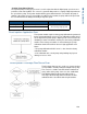
Run Screen
• AutoSwath
Use to enable/disable automatic control of boom section on/off state based upon field boundaries,
prescription files, and previously applied areas.
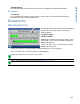
DIAGNOSTICS
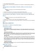
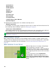
INPUT DIAGNOSTICS
The Input Diagnostic Tab lists the number of Ground
Speed Pulses coming in from the radar to the
Auxiliary Module.
• (A) Switch Inputs
• (B) E2: Foot Box
Additionally, the bottom row of boxes lists the active
switch inputs. These color coded boxes display the
following diagnostics:
• Green: The switch box is connected to the Auxiliary
Module in the On position.
• Black: The switch box is connected to the Auxiliary Module, but is in the Off position.
• Grey: The switch box is not connected to the Auxiliary Module.
Note: The E2 position is the indicator for the foot box.
Note: Other diagnostic settings can be found in “Diagnostics” on page 24.