
User manual
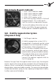

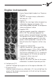


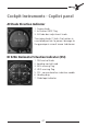


Table Of Contents

44 45
44 45
When operating in clock mode, the current date is displayed by
pushing the DT/AV button (4).
Gyro & Pneumatic Pressure
These gauges indicate the pressure in the
pneumatic and gyro systems. Both systems
are pressurized by bleed air from the engines.
Under normal conditions, pneumatic pres-
sure should be 18psi, gyro pressure should
range between 4.2 und 6.2 inHg.
Inverter & Bus Tie Switches
1: Inverter 1/OFF/2 Selector
2: GYRO/INV Bus Tie Switch
Inverters convert 28V DC power from
the generators to 115/26 VAC 400Hz AC
power. The GYRO/INV Bus Tie Switch (2)
selects either the left or right Main Bus
as the power source for DC power. The
Inverter 1/OFF/2 Selector (1) selects either
Inverter 1 or 2 as active.
Left/Right HTG Test Switches
These two center-locking switches (1 and
2) are used to test the hydraulic topping
governors prior to flight. When operating
properly, with the propeller lever fully
forward and Np set at 1625 RPM (IIXL:
1450RPM), holding the appropriate switch
in the upper „H.T.G. RESET“ position will result in a 85 RPM reduction
in Np. Returning the switch to the center position will return the Np to
1625 RPM (IXL: 1450 RPM).