Add-on for Microsoft Flight Simulator And FS2004! Piper PA-31T Manual
Piper PA-31T Cheyenne X Development: Digital Aviation Graphics & models: Tobias Ahlbrecht Flight Models: Alexander M. Metzger Sounds: Dr. Achim Bürger Programming, Gauges: Hans Hartmann Project Management: Hans Hartmann Manual, documentation: Martin Georg Installer: Andreas Mügge Copyright: © 2007 / Aerosoft GmbH Airport Paderborn/Lippstadt D-33142 Büren, Germany Tel: +49 (0) 29 55 / 76 03-10 Fax: +49 (0) 29 55 / 76 03-33 E-Mail: Internet: info@aerosoft.de www.aerosoft.de www.aerosoft.
Piper PA-31T Cheyenne X Manual Add-on for Microsoft Flight Simulator X 3
Piper PA-31T Cheyenne X Content Introduction ......................................................................6 Configuration ....................................................................8 Saving your settings........................................................... 9 Options ................................................................................ 9 Weight and Balance ......................................................... 10 Sounds volume ............................................
Automated flight ............................................................56 Cheyenne I & IA Bendix-King KFC250 Autopilot & Flight Director ....... 56 KFC250 Autopilot Operation Modes ........................ 60 Cheyenne II & IIXL Bendix-King KFC300 Autopilot & Flight Director ....... 68 Additional KFC300 Autopilot Operation Modes ........ 69 Bendix-King Avionics Paket (Radios) ............................71 KMA 28 Audio Panel Operation ............................... 72 KY 196A COM1/COM2 ...............
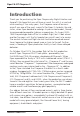
Piper PA-31T Cheyenne X Introduction Thank you for purchasing the Piper Cheyenne by Digital Aviation and Aerosoft. We hope that you will have as much fun with it as we had while creating it. For many years, the Cheyenne series of business aircraft was one of the most successful for Piper. It started in the mid sixties, when Piper decided to redesign its pressurized model „Navajo” to accommodate propeller turbines as propulsion.
The instrumentation is an exact rendition of its real counterparts, based on the „Silver Crown Plus” avionics suite by Bendix-King. Autopilot is either the KFC250 or the KFC300 by Bendix-King, depending on the model you choose. The pressurization controllers are models by Dukes and Garret. A configuration program is provided to help with individual settings. And now we wish you many pleasant hours with our Piper Cheyenne Add-On for the Microsoft Flight Simulator.
Piper PA-31T Cheyenne X Configuration The Piper Cheyenne can be fully configured using the supplied configuration manager.
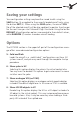
Saving your settings Your configuration settings may be either saved to disk using the SAVE button (3) or applied to the currently loaded aircraft only, using the button EXIT (4). When using the SAVE option, the aircraft CFG file of the selected aircraft will be also updated, to pertain the changes for the next time you start Microsoft Flight Simulator. Using the button DEFAULT all configuration options are reverted to their default values, while RANDOM (2) creates a random aircraft loading.
Piper PA-31T Cheyenne X 9: Show Radar 3D objects in VC Deselecting this option displays the radar as a 2D object instead of a 3D object in the virtual cockpit. This is necessary if you want to add a third-party weather radar at this place. 10: „Active Noise Reduction” (ANR) Sound Set When using the ANR sound set, the internal engine sound is greatly muffled, as the pilot would hear it while wearing Active Noise Reduction (ANR) headphones.
Please note that for the pilot and copilot seats, only men or women may be selected. A detailed weights listing (18) is displayed just below the load editor. If the loading is within limits, the TOTAL WEIGHT value is displayed in green. Overweights are displayed in red. Sounds volume Four sliders are available to individually configure different portions of the sound set: 14: Ambient sounds volume Adjusts the volume level for click sounds and other background noises.
Piper PA-31T Cheyenne X Basics of operation Panel operation Microsoft Flight Simulator traditionally depends heavily upon mouse actions to operate buttons, switches and knobs. Sometimes, click spots may not be 100% intuitive, or the result of your action may depend upon clicking with the left or right mouse button at the correct location. When familiarizing yourself with the panel, it is suggested that you turn on „tool tips”.
Multi-position switches: Multi-position switches have more than one position, and may be turned left/down or up/right. Left-click to move the switch to the left or down, and right-click of right/up movement. Note: You can always use your mouse wheel to operate a multiposition switch. Knobs with one level: Knobs are rotated left/right, or may be rotated completely around. Left-click to rotate the knob to the left, and rightclick to rotate the knob to the right anywhere in the click spot.
Piper PA-31T Cheyenne X Knobs with two levels: Some instruments contain knobs with an inner and an outer ring. In this case, the click area is further divided into a left and a right part. Clicks in the left half of the click spot rotate the outer knob, while the right half adjusts the inner knob. Note that the operation rules for one-level knobs still apply. Note: You can always use your mouse wheel to rotate a knob.
Frequently asked questions (FAQ) VOR/GPS Switch operation: As soon as the NAV1 radio is tuned to a valid ILS frequency, the VOR/ GPS switch changes to VOR and the autopilot to NAV ARM mode. If a valid ILS frequency is in range, the autopilot will follow it´s localizer beam. Valid ILS frequencies are between 108.10 and 111.95 and the decimal part starts with an odd digit: 108.10, 108.15, 108.30, 108.35, 108.50, ..., 108.95, 109.10, 109.15, ..., 111.95.
Piper PA-31T Cheyenne X Cold & Dark state After loading in cold & dark state, wait some time for all engine instruments to show zero before you begin any startup procedures.
General Data Power plants Cheyenne I Cheyenne IA Number of engines Rated Horsepower Propeller Speed Cheyenne IIXL 2 Pratt & Whitney (UACL) Manufacturer Model number Cheyenne II PT6A-11s PT6A-28s 620 PS 500 PS 2200 rpm Dry weight PT6A-135s 2200 rpm 317 lbs. 1900 rpm 323 lbs.
Piper PA-31T Cheyenne X Fuel Cheyenne I Cheyenne IA Cheyenne II Capacity without tip tanks 308 gal. with tip tanks 374 gal. Usable fuel without tip tanks 300 gal. with Tip Tanks 366 gal. Fuel grade Cheyenne IIXL Jet A Weights Cheyenne II Cheyenne IIXL Ramp Weight Cheyenne I 8750 lbs. 9050 lbs. 9540 lbs. Standard Empty Weight 5110 lbs. 4976 lbs. 5874 lbs. Maximum Useful Load 3640 lbs. 4074 lbs. 4053 lbs. Max. Takoff Weight 8700 lbs. 9000 lbs. 9474 lbs. Max.
Abbrevations and Terminology (a) General Airspeed Terminology CAS Calibrated Airspeed means the indicated speed of an aircraft, corrected for position and instrument error. Calibrated Airspeed is equal to true airspeed in standard atmosphere at sea level. KCAS Calibrated Airspeed expressed in „Knots“. GS Ground Speed is the speed of an airplane relative to the ground. IAS Indicated Airspeed is the speed of an aircraft as shown on the airspeed indicator when corrected for instrument error.
Piper PA-31T Cheyenne X VLO Maximum Landing Gear Operating Speed is the maximum speed at which the landing gear can be safely extended or retracted. VMCA Air Minimum Control Speed is the minimum flight speed at which the airplane is directionally controllable as determined in accordance with Federal Aviation Regulations. VMO/MMO Maximum Operating Speed is the speed limit that may not be deliberately exceeded in normal flight operations. V is expressed in Knots and M in mach number.
(b) Meteorological Terminology ISA International Standard Atmosphere in which: (1) The air is a dry perfect gas; (2) The temperature at sea level is 15°C (59°F) (3) The pressure at sea level is 29.92 inches (1013.2 mb). (4) The temperature gradient from sea level to the altitude at which the temperature is -56.5°C (-69.7°F) is -0.00198°C (-0.003564°F) per foot and zero above that altitude.
Piper PA-31T Cheyenne X (d) Engine Controls and Instruments Power Control The lever which modulates engine power from reverse Lever thrust through takeoff power. Propeller The lever which requests a propeller governor to maintain Control Lever propeller rpm at a selected value or feathers a propeller. Condition Lever The lever which controls fuel flow to an engine. Beta Range The region where the propeller blade angle is between the fine pitch stop and the maximum reverse pitch setting.
Route Segment A part of a route. Each end of that part is identified by (1) a geographical location or (2) a point at which a definite radio fix can be established. (f) Weight and Balance Terminology Usable Fuel Fuel available for flight planning. Unusable Fuel Fuel remaining after a run out test has been completed in accordance with governmental regulations. Standard Empty Weight of a standard airplane including unusable fuel, Weight full operating fluids and full oil.
Piper PA-31T Cheyenne X Instrument panels The Piper Cheyenne offers two ways to access the cockpit: A classic 2D cockpit view, and a 3D virtual cockpit view. By default, Microsoft Flightsimulator X will load the aircraft in 3D virtual cockpit view. In classic 2D panel view, 5 different instrument panels are provided: Normal view, approach view, landing view, IFR view, VFR view and copilot view. In addition, Microsoft Flightsimulator X provides a Minipanel view and a view mode where no panel is displayed.
IFR view: 25
Piper PA-31T Cheyenne X Approach/Landing view: Aerosoft GmbH 2007 26
VFR view: From the 2D cocpit, several sub-panels or view options may be selected by hidden clickspots and hotkeys.
Piper PA-31T Cheyenne X Panel navigation by clickspots In addition to these clickspots, panel view may also be selected by hotkeys: • SHIFT-2: Overhead panel • SHIFT-3: Center pedestal • SHIFT-4: Fuel crossfeed panel • SHIFT-5: ADI/HSI zoom • SHIFT-6: Right radio stack • SHIFT-7: Configuration screen • SHIFT-8: Autopilot zoom • SHIFT-9: VOR2 & Alt preselect Sub-panels can be closed by clicking in the upper-right corner of the background bitmap.
The following additional hidden clickspots are available: • ADI: Zooms the ADI and HSI • Trimble GPS glass display: opens the map view window • Area between radio stack and Glareshield: Displays the right radio stack • Registration plate: Opens the kneeboard • Fuel Flow gauges: Fuel selector window • Microphone (Copilot view): Microsoft Flight Simulator ATC window • Yoke shaft: Displays or hides the yoke • Altitude preselector: Display the NAV2 gauge 29
Piper PA-31T Cheyenne X Overview Pilot Panel 1: 2: 3: 4: 5: 6: 7: 8: 9: 10: 11: 12: 13: 14: Attitude Direction Indicator Horizontal Situation Indicator Altimeter Vertical Speed Indicator & TCAS Radar Altimeter True Airspeed Indicator Turn & Bank Indicator KNI 582 RMI OAT Indicator Clock Cabin Pressure Test Switch Gyro Pressure Pneumatic Pressure Inverter & Bus Tie Switches Aerosoft GmbH 2007 30 15: 16: 17: 18: 19: 20: 21: 22: 23: 24: 25: 26: 27: 28: Engine Torque ITT Gauge Propeller RPM Gas Generator
29: 30: 31: 32: 33: 34: 35: 36: KM551 VOR Indicator Flap Control & Position Pressurization Controller H.T.G.
Piper PA-31T Cheyenne X Overhead-Panel (Cheyenne I, IA and II) 1: 2: 3: 4: 5: 6: 7: 8: 9: 10: 11: 12: 13: 14: 15: 16: Left gyro controls Right gyro controls Left Generator Ammeter Voltmeter Right Generator Ammeter Seat Belts Switch Dome Light No Smoking Switch Exit Lights Switch Wing Lights Switch Landing Lights Switch Taxi Lights Switch Anti-Collision Lights Switch Position Lights Switch Battery Master Switch Windshield Heat Switches Aerosoft GmbH 2007 17: 18: 19: 20: 21: 22: 23: 24: 25: 26: 27: 28:
Overhead-Panel (Cheyenne IIXL) 1: 2: 3: 4: 5: 6: 7: 8: 9: 10: 11: 12: 13: 14: 15: Left gyro controls Right gyro controls Left Generator Ammeter Voltmeter Right Generator Ammeter Seat Belts Switch Dome Light No Smoking Switch Exit Lights Switch Wing Lights Switch Landing Lights Switch Taxi Lights Switch Anti-Collision Lights Switch Position Lights Switch Battery Master Switch 16: 17: 18: 19: 20: 21: 22: 23: 24: 25: 26: 27: 28: 29: 33 Windshield Heat Switches Pitot Heat Switches Surface Deice Switch Tail
Piper PA-31T Cheyenne X Copilot 1: 2: 3: 4: 5: 6: 7: 8: 9: 10: 11: 12: 13: 14: 15: 16: 17: KMA 28 Audio Panel KY 196A COM1 Radio KY 196A COM2 Radio KN 53 NAV1 Radio KN 53 NAV2 Radio Trimble 2000 GPS KR 87 ADF1 KAS 297 Altitude Preselector Flap Control & Position Avionic control panel KT 76C Transponder 1 & 2 KR 87 ADF2 Ground Clearance Switch Static Pressure Source True Airspeed Indicator Turn and Bank Indicator Fuel Totalizer Aerosoft GmbH 2007 34 18: Flaps Position Selector 19: Windshield Wiper Cont
Center Pedestal Cheyenne I/IA Cheyenne II/IIXL 1: 2: 3: 4: 1: Power Levers 2: Propeller Levers 3: Condition Levers (IIXL only: Low Idle and High Idle positions) 4: KMC 340 Autopilot and Yaw Mode Controller 5: Elevator Trim Wheel 6: Rudder Trim Wheel 7: Aileron Trim Wheel Power Levers Propeller Levers Condition Levers KC 290/291 Autopilot and Yaw Mode Controller 5: Elevator Trim Wheel 6: Rudder Trim Wheel 7: Aileron Trim Wheel 35
Piper PA-31T Cheyenne X Yoke and Fuel crossfeed windows Control yokes Two different models of yokes are installed in the Piper Cheyenne. The Cheyenne IA and IIXL are equipped with variant (1), while the Cheyenne I and II use variant (2). I und II enthalten Variante (2). 3: Elevator trim up/down 4: Autopilot disconnect 5: Toggle Microsoft ATC window 6: Flight director pitch synch button Synchronizes the flight director with the current pitch.
Primary Instruments - Pilot panel KCI 310 Attitude Direction Indicator (ADI) 1: Attitude Indicator 2: Flight Director 3: Glidepath Indicator 4: Localizer signal indicator 5: Decision Height Indicator 6: RNAV Indicator: Illuminated when „GPS“ is selected as the NAV source. Requires a flight plan to be active in the Trimble GPS.
Piper PA-31T Cheyenne X Altimeter 1: Altitude readout, numeric 2: Pressure in millibars (QNH) 3: Altimeter pressure in Inches 4: Barometric pressure setting knob Hint: The „B“ key in Microsoft Flight Simulator sets the altimeter to local pressure, or standard pressure, depending on the aircraft´s altitude. The transistion altitude is defined as 18.000ft worldwide.
Vertical Speed Indicator & TCAS Display 1: Indicates climb or descend rate in ft/min x 100 2: Above/Level/Below selector. switches display of TCAS targets between the areas above the aircraft (up to 9.999ft above and 2500ft below - „ABV“), at aircraft´s level (2.500ft above and below „LVL“) and below the aircraft (up to 2500ft above and 9.999ft below - „BLW“). Only modes ABV and BLW are indicated on the display. 3: TCAS range selector. Switches between 6nm and 12nm TCASRange.
Piper PA-31T Cheyenne X Airspeed Indicator (ASI) 1: Indicated Airspeed Indicator 2: Blue line: Best rate of climb speed - single engine 3: Red Marker: Air minimum control speed 4: Green arc: Normal operating range 5: White arc: Flaps extend range Pneumatic Turn & Slip Indicator 1: Turn indicator pointer 2: Slip indicator ball The turn and slip indicator is actually two instruments in one.
RMI-30 Radio Magnetic Indicator 1: VOR1 / ADF1 indicator needle 2: VOR2 / ADF2 indicator needle 3: VOR1 / ADF1 selector switch 4: VOR2 / ADF2 selector switch 5: HDG Warning Flag: Indicates a failure of the gyro compass. This usually results from the inverter not powering the gyro. Course and heading information are supplied to the RMI by the gyro compasses.
Piper PA-31T Cheyenne X Also incorporated in the SAS is a stall margin indicator (1), which receives its signal from the SAS computer. The indicator provides visual input to the pilot of the ratio of present speed to stall speed for any airplane configuration. The indicator dial is marked with five colorcoded zones: red (stall), red and black barber pole (stall warning), yellow (slow), white (30% above stall) and green (speed greater than 30% above stall).
Engine instruments 1: Engine Torque (digital readout on Cheyenne IIXL only) Indicates the engine torque, calibrated in foot-pounds x 100. 2: Engine ITT Indicates the interstage turbine temperature, calibrated in degrees centigrade x 100, measured by probes between the compressor turbine and power turbine. 3: Propeller RPM Indicates propeller speed (Np), calibrated in RPM x 100. The rotational speed of the power turbine is lowered through the reduction gearbox which drives the propeller.
Piper PA-31T Cheyenne X 8: Oil temperature Indicates engine oil temperature, calibrated in degrees centigrade transmitted from the output of the oil pressure pump prior to the oil entring the engine lubrication channels. Secondary instruments - Pilot panel OAT Indicator Shows the outside air temperature. Gauge is scaled in both Celsius °C and Fahrenheit °F. Astrotech LC2 Clock & Timer The Astrotech LC2 works as both a clock and a timer. Per default it is configured for 24hrs display.
When operating in clock mode, the current date is displayed by pushing the DT/AV button (4). Gyro & Pneumatic Pressure These gauges indicate the pressure in the pneumatic and gyro systems. Both systems are pressurized by bleed air from the engines. Under normal conditions, pneumatic pressure should be 18psi, gyro pressure should range between 4.2 und 6.2 inHg.
Piper PA-31T Cheyenne X Oxygen Control Knob The oxygen control knob controls the cableoperated manual shutoff valve. When pulled out, oxygen is supplied to the cockpit and cabin outlets. A 22 or 48 cubic foot oxygen supply bottle is installed aft of the baggage compartment. The oxygen system is designed to provide emergency oxygen for the crew and passengers for flight at altitudes above 10.000 feet.
Cockpit Instruments - Copilot panel Attitude Direction Indicator 1: Caging knob 2: Instrument INOP flag 3: Attitude bars adjustment knob The caging knob (1) locks the horizon in a centered position to prevent damage to the gyroscope in case of severe turbulences.
Piper PA-31T Cheyenne X RMI-30 Radio Magnetic Indicator 1: VOR1 / ADF1 indicator needle 2: VOR2 / ADF2 indicator needle 3: VOR1 / ADF1 selector 4: VOR2 / ADF2 selector 5: HDG Warning Flag: Indicates a failure of the gyro compass. This usually results from the inverter not powering the gyro. Course and heading information are supplied to the RMI by the gyro compasses. Inverter power is needed to operate the gyros (for proper operation check inverter and bus tie switches).
Altimeter 1: Altitude indicator needle 2: Pressure in millibars (QNH) 3: Altimeter pressure in Inches 4: Barometric pressure setting knob Hint: The „B“ key in Microsoft Flight Simulator sets the altimeter to local pressure, or standard pressure, depending on the aircraft´s altitude. The transistion altitude is defined as 18.000ft worldwide. Vertical Speed Indicator (analogue) 1: VS needle, indicates climb/descend rate in feet/min x 100.
Piper PA-31T Cheyenne X Pneumatic Turn & Slip Indicator 1: Turn indicator pointer 2: Slip indicator ball The turn and slip indicator is actually two instruments in one. The turn portion is a pointer (1), attached to an air-driven gyro, which indicates the airplane´s turning rate in degrees per second. An indicated standard rate turn should show a turning rate of 3° per second on the directional gyro. The slip portion indicates gravitational and centrifugal forces acting on the airplane.
Flaps Position Indicator & Test Switch 1: Flaps position indicator needle 2: Test switch 3: Flaps position lever. Flaps can be set to the following positions: 0°, 15°, 40°. In the real aircraft, flaps are infinitely variable between 0° and 40°. Unfortunately, this cannot be simulated in MIcrosoft Flight Simulator, and as this feature is not used under normal circumstances, it isn´t simulated in this package. Ground Clearance Switch Provides power to the audio panel, COM1 and NAV1 receivers when pushed.
Piper PA-31T Cheyenne X Environmental Controls - Copilot Environmental Controls - Cheyenne I, IA and II 1: Windshield Wiper control knob 7: Dehumider Control switch 2: Heater Fuel Flow control switch 8: Oxygen Supply Pressure gauge 3: Environmental Control MODE switch 9: Fuel totalizer 4: Environmental Control MASTER switch 10: Defroster 5: Cabin Temperature control knob 11: Yoke clickspot 6: Manual Mode switch The cabin comfort control panel contains all the controls needed to operate the heating, coolin
The air conditioning system can be operated either independently or in conjunction with the heater, depending upon the mode selected on the cabin comfort control panel. During normal operation, when the MODE switch (3) is in the AUTO position, a thermostat, adjustable by the TEMP knob (5), signals an electronic controller which turns on the air conditioner until the cabin reaches the selected temperature.
Piper PA-31T Cheyenne X is provided by engine bleed air through a bleed-air shutoff valve and bleed-air ducts from each engine. Bleed air to the ECS is controlled by a pressure regulator/shutoff valve. This valve can be selected for high and low airflow via the ECS SELECT Switch (3). The ECS SELECT Switch (3) must be in the LO position for engine starting, takoff and landing. The HI position may be used on the ground to provide maximum heating or cooling.
mode switch (2) is moved to MAN. The temperature selector rheostat knob is now deactivated, and the MAN TEMP CONT Switch (5) is armed. Holding this switch to the HEAT or centered position applies electrical power directly to the selected side of the hot air bypass valve motor, and the valve will open or close accordingly. Two cabin blowers are located in recirculation fan boxes on the left and right sides of the cabin forward the of the wing door.
Piper PA-31T Cheyenne X Automated flight Cheyenne I & IA - Bendix-King KFC250 Autopilot & Flight Director KC290 Mode Controller: 1: FD/AP Vertical Trim 7: Approach mode (APPR) (Pitch Attitude/Altitude) (ILS/VOR) 2: Heading mode (HDG) 8: Autopilot (AP) 3: Flight Director (FD) 9: Autopilot Test Button 4: Altitude hold mode (ALT) 10: Go-Around mode Clickspot 5: NAV mode (NAV) (VOR/GPS) 6: Reverse Locator (Backcourse) mode (BC) KC291 Yaw Mode Controller: 11: Yaw Damper Engage/Disengage 12: Annunciator Light Th
Basic Attitude Reference Mode Activated with „power on” (AP) but with no modes selected. The Flight Command indicator (Flight director bars in the ADI) and horizontal situation indicator (HSI) will display existing attitude and heading. The Command V-bar is retracted out of view until a Flight Director/Autopilot mode has been selected. Flight Director (FD) Command V-bar will call for wings level. The pitch attitude of the aircraft will remain the same as at the time of mode selection.
Piper PA-31T Cheyenne X Back Course (BC) With back course selected in approach mode, the system when capturing will command the bank necessary to capture and track a reverse LOC course. Glideslope is locked out. The inbound front approach course is always set on the HSI to enable you to make course corrections toward the needle rather than away from the needle on the HSI.
PITCH ATTITUDE SELECTOR KNOB OPERATION Depending on the selected autopilot mode, clicking the UP/DN positions of the PITCH ATTITUDE SELECTOR KNOB produces the following results: Pitch Modus: +/- 0.5° pitch per click Kein Modus: Trim adjust +/- 1 per click. Equals pressing the 1 or 7 keys on the numeric keypad.
Piper PA-31T Cheyenne X KFC250 Autopilot Operation Modes There are twelve (12) modes of operation that are provided by the KFC 250 system to offer the pilot Flight Director/Autopilot commands in response to his selection of desired modes on the Mode Controller. Most of these modes are activated by pushbutton switches on the Mode Controller. These pushbuttons operate with alternate action.
Vertical Trim switch on the Mode Controller may also be used to adjust the selected pitch attitude up or down at approx. 1 degree/second. Special note: The FD mode must be activated before the Autopilot can be engaged. AUTOPILOT Engagement The AUTOPILOT is engaged by moving the AP toggle switch on the Mode Controller to the ON position. Note that the AP and the YAW DAMP (YD) switches are wired so that the YAW DAMP mode is automatically engaged with the AP switch.
Piper PA-31T Cheyenne X HEADING SELECT/PRESELECT Mode (HDG SEL) Select a desired heading by positioning the heading „bug” on the HSI. This is done with the HDG knob on the HSI. Depress the HDG button on the Mode Controller to activate the HDG SEL mode. „HDG SEL” will light on the Annunciator Panel and a computed, visually displayed bank command is shown on the FCI. Following this bank command, the aircraft will bank and roll out on the desired preselected heading.
NAVIGATION (NAV ARM and NAV CPLD) Mode The NAV mode provides visual bank commands on the Flight Command Indicator and deviation guidance on the HSI to intercept and track a VOR course or an GPS course. Operation of the NAV mode requires the pilot to: 1. Tune the frequency of the selected VOR (or VORTAC) station. 2. Set the HSI course pointer on the desired course. 3. Establish angle of intercept by setting the heading „bug” and activate „HDG” mode. 4. Depress the NAV button on the Mode Controller.
Piper PA-31T Cheyenne X The NAV mode is cancelled by depressing the NAV button, or selecting HDG (when in NAV coupled) or APPR modes, or pushing FD to „OFF“. Caution: The NAV mode of operation will continue to provide airplane control without a valid VOR/LOC signal (NAV flag in view). Special note: When an ILS frequency in range is tuned into the NAV1 radio, a possible selected VOR GPS mode is cancelled, and the autopilot reverts to NAV mode (i.e. the autopilot follows the localizer signal only!).
tracking. VOR/LOC deviation is shown on the HSI, and actual crab angle will be shown by offset of the course arrow from the lubber line. Throughout APPR mode operation, LOC and Glideslope deviation or VOR deviation are displayed in the HSI. If the Autopilot is engaged during operation in the APPR mode, automatic steering response will follow the command display on the FCI. The Glideslope mode is armed for automatic capture if LOC front course capture has occurred.
Piper PA-31T Cheyenne X tomatic Glideslope capture is „locked out” by the switching circuitry. Localizer deviation on HSI will have the proper sensing if the front inbound Localizer course was set on the HSI. Special note: Back course mode is only available after selecting APPR mode. GO-AROUND Mode The Go-Around mode is primarily designed to assist the pilot in establishing the proper pitch attitude under missed approach conditions.
ALTITUDE SELECT (ALT ARM) Mode This mode allows the pilot to select an altitude and, upon approaching that selected altitude, obtain an automatic visual pitch command on the FCI to capture and hold the preselected altitude. To operate in this mode the pilot must: 1. Set the desired altitude into the „selected altitude” window of the KAS 297 Altitude Selector. 2. Establish a climb or descent as appropriate. 3. Depress the ARM button on the Altitude Selector.
Piper PA-31T Cheyenne X the aircraft altitude to match resetting of the altimeter, or to make short descent segments during a nonprecision approach. The ALT HOLD mode is cancelled by automatic Glideslope capture or selection of ALT ARM, or GO-AROUND modes, or selection of FLT DIR to OFF.
This chapter describes only the differences to the KFC250 Autopilot & Flight Director, mentioned previously. For complete Autopilot reference, refer to Chapter Automated flight. KAP315 ANNUNCIATOR PANEL 1: Autopilot Mode Anzeigen The KAP315 Annunciator Panel provides the pilot with continuous information on system operating status. It shows modes in operation, as well as modes „armed” prior to capture. Clicking on the annunciator panel opens a zoomed autopilot window.
Piper PA-31T Cheyenne X SPEED PROFILE (SPD PRF) mode The speed profile mode is used primarily in climb or descend. The pilot engages SPEED PROFILE at the speed appropriate to his altitude at the time of engagement. Or he adjusts to the appropriate speed for his altitude with the vertical trim switch after engagement. The reference airspeed may be adjusted at a rate of two knots per second by use of the Vertical Trim switch on the Mode Controller.
Bendix-King Avionics Paket (Radios) The Piper Cheyenne is equipped with a complete avionics suite, the „Silver Crown Plus“ series by Bendix-King. This suite is composed of the KMA 28 Audio Panel, two KY 196A VHF communication receivers, two KY 53 navigations receivers, two KR 87 ADF receivers, and two KT 76C mode C transponders.
Piper PA-31T Cheyenne X KMA 28 Audio Panel Operation Intercom Volume Works as the power switch for the KMA 28 audio panel. Volume selection is not modeled. Receive Audio Selector Routes the output from the selected receivers to the speakers. In this release, COM1, COM2, NAV1,NAV2, MKR, ADF and DME are modelled. When using Squawkbox 3 or any Squawkbox 3-compatible pilot client for online flying, COM1 or COM2 are flashing when other stations are transmitting on the selected radio channel.
KY 196A COM1/COM2 Communications Radio Operation Power up When you turn the ON/OFF/Volume knob clockwise to the „ON” position, your unit will display the frequencies last used in the „USE” and „STBY” (standby) windows. Note: As with all avionics, the KY 196A should be turned on only after engine startup. This simple precaution will help protect the solid-state circuitry and extend the operating life of your equipment.
Piper PA-31T Cheyenne X 2. Press the transfer button to activate the new frequency. The newly entered frequency in the „STBY” window flipflops with the frequency in the „USE” window. This new frequency is now available for use. Program Mode The Program Mode is used to program frequencies for use in the Channel Mode. 1. Depress the channel (CHAN) button for more than two seconds, until the channel number (to the right of the standby frequency) begins flashing.
Channel Mode The Channel Mode is used to recall preset frequencies stored in memory. 1. To enter the Channel Mode momentarily, push the channel button while in the Frequency Mode. The active frequency remains displayed in the „USE” window, and the last used channel number and its associated frequency are displayed in the „CHAN” and „STBY” windows. If no channels have been programmed, channel 1 automatically disappears and dashes are displayed in the „STBY” window. 2.
Piper PA-31T Cheyenne X Direct Tune Mode The Direct Tune Mode is entered by pressing and holding the transfer button for longer than two seconds. The „STBY” frequency will disappear and the frequency in the active window can be changed with the frequency selection knobs. Momentarily pushing the transfer button will return the unit to the Frequency Mode (normal operation). The „STBY” frequency displayed prior to entering the Direct Tune Mode will return unchanged.
108.95 with MHz knob rotation, or 117.00 with kHz knob rotation). DME and optional internal glideslope channeling are also controlled by these selector knobs. NAV Frequency Operation The desired operating frequency is first entered into the standby display. To activate, push the transfer button. This will interchange the frequencies in the ‘use’ and ‘standby’ displays and tune the receiver to the new operating frequency.
Piper PA-31T Cheyenne X Frequency Selection The active frequency (to which the ADF is tuned) is displayed in the left side of the window at all times. A standby frequency is displayed in the right side when „FRQ” is annunciated. The standby frequency is placed in „blind” memory when either FLT (Flight Time) or ET (Elapsed Time) mode is selected. With „FRQ” annunciated, the standby frequency is selected using the frequency select knobs which may be rotated either clockwise or counterclockwise.
Operating the Timers The flight timer will always be automatically reset to :00 whenever power is interrupted either by the avionics master switch or the unit’s ON/OFF switch. Operation of the flight timer is automatic. The timer is started in the moment the aircraft takes off. It will stop at the moment the aircraft touches down during landing. The elapsed timer may be reset back to :00 by pressing the SET/RST button. It will then start counting up again.
Piper PA-31T Cheyenne X KT 76C Panel-mounted Transponder Operation About Transponders Your Honeywell Bendix/King transponder is a radio transmitter and receiver which operates on radar frequencies. Receiving ground radar interrogations at 1030 MHz, it returns a coded response of pulses to groundbased radar on a frequency of 1090 MHz. As with other Mode A/Mode C transponders, the KT 76C replies with any one of 4,096 codes, which differ in the position and number of pulses transmitted.
Operating the KT 76C Before starting your aircraft’s engine, make sure that the KT 76C function selector knob, or your avionics master, is turned to OFF. After engine start, turn the function selector knob to SBY (standby). Give your transponder about 45 seconds to become operational. Select the proper reply code by pressing the desired code entry buttons. The reply code will be displayed in the code window.
Piper PA-31T Cheyenne X VFR Button Momentarily pressing the VFR button will enter a pre-programmed VFR code, typically 1200, in the code window. Pressing and holding the VFR button for two seconds will cause the last active code to be displayed. Depending on your home country, it may be desired to set the default VFR code to a code other than 1200. To change the default VFR code, edit the PA31.CFG file in the \Digital Aviation\ PA31 Cheyenne\ folder using a standard text file editor.
Trimble 2000 Approach Plus GPS Introduction The Piper Cheyenne is not exactly a new aircraft. Most of them were built during the 70s and 80s of the last century. The models in this package represent the Piper Cheyenne as it was built from 1981 on. By that time, modern navigation systems like GPS (introduced 1995) didn‘t exist and navigation on general aviation aircraft was done using common NAV radios and ADFs. Today, the situation is different.
Piper PA-31T Cheyenne X User Interface The Trimble Approach Plus is controlled by nine buttons and two concentric knobs. The Power Switch is located at the upper edge of the display. Use this switch to switch the GPS on and off. The Outer Knob is used to control the input cursor and to flip between display pages. The Inner Knob is used to select items. Switches the GPS to Navigation mode.
Switches to the Flight Plan mode. This mode is used to select stored or add new flight plans. The Calculator mode shows a variety of data calculated by the GPS. This includes atmospheric and fuel data. The Auxilliary mode is used to import flight plans from FSX. The Direct key is used to activate a flight plan or fly directly to a waypoint. The Enter key is used to confirm selections made with the concentric knobs.
Piper PA-31T Cheyenne X Keyboard Entry Mode On the real Trimble, you can only select or enter waypoints by using the two concentric knob. This is already hard to do, but it‘s even worse if it must be done with mouse clicks. To make data entry more comfortable, we added a keyboard entry mode which is activated by the SCROLL LOCK key. This key toggles the keyboard input mode on or off. As soon as it‘s on, „KBD“ will appear in the upper right corner of the GPS display.
Enter Key: Return, Keypad 5 or Enter. Importing FS Flight Plans To avoid the hassle of entering a flight plan into the Trimble, a function to import a flight plan from FSX is available. This requires three simple steps: • First, go to the FSX Flight Planner (Menu „Flights | Flight Planner“) and create or load the desired flight plan. • Click on the Trimble. If a flight plan is loaded it displays „PRESS ENT TO IMPORT FS FLIGHT PLAN“. • Click to import and activate the flight plan.
Piper PA-31T Cheyenne X Simulation vs. Reality: Unimplemented Functions The real Trimble is quite hard to use due to it‘s limited display capabilities (2 lines with 20 characters each) and overloaded user interface.
Pressurization system Dukes Pressurization Controller (Cheyenne I & IA) Garret Pressurization Controller (Cheyenne II & IIXL) 1: Cabin rate of climb gauge 4: Cabin altitude controller 2: Cabin altitude gauge 5: Cabin pressure test/dump 3: Cabin rate of change control switch (Garret only) Defaults to 500 ft/min cabin change rate May be adjusted to a minimum of 100 ft/min or a maximum of 1000 ft/min (Garret: 2500 ft/min) Pressurization air for the Piper Cheyenne is obtained by use of high pressure engine com
Piper PA-31T Cheyenne X air outlets. When the control is in the OUTSIDE AIR position, the air is not needed for pressurization. Air is then routed below the cabin floor and overboard. During ground operations, to prevent fumes from other aircraft entering the cabin, the control may be placed in the RECIRCULATED AIR position. In this position, no outside air enters the system. Restrict continuous operation in the recirculated air position to 15 minutes.
altitude instrument (2), indicates the differential pressure between the cabin and the outside atmosphere. Note: A residual pressure of approximately .25 PSI will show on the differential pressure gauge at any time pressurization is selected and the aircraft is operating lower than the cabin altitude selected. Do not land when aircraft is pressurized above .3 PSI A warning light on the annunciator display warns the pilot should the cabin altitude go above 10.500 feet (Garret: 11.500 feet to 12.
Piper PA-31T Cheyenne X TCAS (with digital VSI only) TCAS in digital VSI - symbol explanation: 1: Vertical speed needle 2: TCAS display centre (own aircraft symbol) 3: 2nm radius circle 4: RA: Vertical rate to be avoided (red) 5: RA: Required vertical rate (green) 6: Display range 7: Target symbol 8: Vertical trend arrow (up or down) 9: Relative altitude (ft x 100) Own Aircraft. Airplane Symbol in White or Cyan. Non Intruding Traffic Altitude Unknown Open Diamond in White or Cyan.
147A. Literally all features of the logic are implemented with the exception of TCAS/TCAS resolution advisory (RA) negotiation and Mode S ground stations. Traffic Display Symbology Both color and shape are used to assist the pilot in interpreting the displayed information. The own aircraft is depicted as either a white or cyan arrowhead or airplane-like symbol. The location of the own aircraft symbol on the display is dependent on the display implementation.
Piper PA-31T Cheyenne X tude information is preceded by a + sign. When the intruder is below the own aircraft, a „-” sign precedes the relative altitude information. The altitude information is displayed in the same color as the aircraft symbol. An arrow is displayed immediately to the right of a traffic symbol when the target aircraft is climbing or descending at more than 600 fpm. An up arrow is used for a climbing aircraft; a down arrow is used for a descending aircraft.
Flight Tutorial Introduction When compared to smaller piston-engine powered airplanes, flying a fast turboprop aircraft like the Piper Cheyenne can be quite a challenge. Besides the faster speed, the aircraft requires precise flying techniques and some understanding about the aircrafts systems and avionics. This tutorial is intended to introduce you to the Piper Cheyenne by giving some hints about how to fly this plane.
Piper PA-31T Cheyenne X Engine start-up When entering the cold & dark aircraft, first turn ON the battery. Next, activate the anti-collision light to signal other traffic on the airport that you will soon start your engines. Check that the prop levers are in FULL FORWARD position (IIXL only: FEATHERED position), and that your parking brake is SET. Next, switch ON fuel pump number 1 or 2 on the engine to be started, set the ignition switch to MANUAL, and set the yellow starter switch to the START position.
for shorter runways). When arriving at the holding position, check your flight controls again for free movement. To prepare for automatic flight, activate the flight director (FD) and select the first altitude using the altitude preselector. Program your GPS, if desired, and dial in your assigned transponder code into transponder 1. Activate the environmental systems, and set the pressurization system. If your cruise altitude is below ca. 12.000 feet, set the cabin altitude to 500 feet above field elevation.
Piper PA-31T Cheyenne X Take off When all preflight checks are completed and you are ready for takeoff, report “ready for departure” to tower. When takeoff clearance is received, switch your transponder from SBY to ALT, turn ON the landing lights, the strobes and the recognition lights, and enter the runway to taxi into position. Gently move the power levers forward to about 50% of its full range, and monitor torque and ITT to rise.
Climb To achieve an appropriate climb configuration, reduce propeller RPM to 1900 or 2000 RPM, as desired (check the performance charts for appropriate RPM settings). When passing the transition altitude, set your altimeter to standard pressure (29.92 inches or 1013 hpa). Altitudes above the transition altitude are referred to as “flight levels”. As the landing gear is already retracted, turn OFF the landing lights. No-smoking and seatbelt signs may be set as desired.
Piper PA-31T Cheyenne X Cruise When cruise level is reached, apply recommended cruise power settings, as indicated on the performance tables. For example, a typical cruise in the Cheyenne I at FL240 means 833 ft-lb torque at 2000 RPM, which will result in around 230 kts TAS cruising speed. Some Cheyenne models also differentiate between Maximum Cruise Power (basically the maximum speed you can achieve) and Economy Cruise Power, which offers the best trade between flight time and range.
Landing When reaching the runway approach lights, set flaps to full (40°) and increase the propeller levers slowly to maximum RPM (Cheyenne II and IIXL only). The speed depletes slowly, and with 500 ft-lb torque, and your airspeed at the blue line you are fully configured for final approach. Latest at 200 ft AGL switch off the autopilot and the yaw damper to continue the approach manually. When passing 50 feet AGL prepare to flare.