
User manual


Page 44
Aircraft Operation Manual
Piper Cheyenne I, IA, II, IIXL
For ight simulation use only
1
2
3
1
2
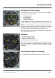
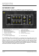
Fuel Quantity Gauge
1: Left fuel tank indicator
2: Right fuel tank indicator
Scale in lbs x 100.
1 2
Airspeed Indicator (ASI)
1: Indicated Airspeed Indicator
2: Red line: Air minimum control speed
3: Blue line: Best rate of climb speed - single engine
4: Green arc: Normal operating range
5: White arc: Flaps extend range
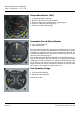
Pneumatic Turn & Slip Indicator
1: Turn indicator pointer
2: Slip indicator ball
The turn and slip indicator is actually two instruments in one. The
turn portion is a pointer (1), attached to an air-driven gyro, which
indicates the airplane´s turning rate in degrees per second. An
indicated standard rate turn should show a turning rate of 3° per
second on the directional gyro.
The slip portion indicates gravitational and centrifugal forces ac-
ting on the airplane. The slip indicator is a simple inclinometer
comprised of a ball contained in a sealed, liquid lled glass tube
(2). In a skip or slip, the rate of turn is too fast or too slow for the
angle of bank and will be indicated by the ball (2) moving from
the center to the outside or inside of the turn.
4
5