
User manual


Page 37
Aircraft Operation Manual
Piper Cheyenne I, IA, II, IIXL
For ight simulation use only
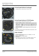
Airspeed Indicator (ASI)
1: Indicated Airspeed Indicator
2: Blue line: Best rate of climb speed - single engine
3: Red Marker: Air minimum control speed
4: Green arc: Normal operating range
5: White arc: Flaps extend range
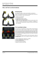
Pneumatic Turn & Slip Indicator
1: Turn indicator pointer
2: Slip indicator ball
The turn and slip indicator is actually two instruments in one. The
turn portion is a pointer (1), attached to an air-driven gyro, which
indicates the airplane´s turning rate in degrees per second. An
indicated standard rate turn should show a turning rate of 3° per
second on the directional gyro.
The slip portion indicates gravitational and centrifugal forces ac-
ting on the airplane. The slip indicator is a simple inclinometer
comprised of a ball contained in a sealed, liquid lled glass tube
(2). In a skip or slip, the rate of turn is too fast or too slow for the
angle of bank and will be indicated by the ball (2) moving from
the center to the outside or inside of the turn.
1
2
1
3
RMI-30 Radio Magnetic Indicator
1: VOR1 / ADF1 indicator needle
2: VOR2 / ADF2 indicator needle
3: VOR1 / ADF1 selector switch
4: VOR2 / ADF2 selector switch
5: HDG Warning Flag: Indicates a failure of the gyro compass.
This usually results from the inverter not powering the gyro.
Course and heading information are supplied to the RMI by the
gyro compasses. Inverter power is needed to operate the gyros
(for proper operation check inverter and bus tie switches).
1
2
3
4
5
4
5
2