
User manual

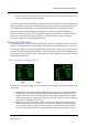
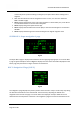


Table Of Contents
- PBY Catalina
- Introduction
- System requirements
- Credits
- Copyrights
- Contact support
- Models and versions
- Limitations
- Failure model and special features
- Aerosoft Sound Control
- Flight model
- Using the switches and knobs
- Interactive Checklist
- Avionics, 1940’s military cockpit
- Avionics, modern cockpit
- Engine Settings
- Mission
- Appendix A: Simplified checklist
- Appendix B: KX 165A TSO
- Appendix C: KLN-90B User Manual
- INTRODUCTION
- OVERVIEW
- DEFINITIONS:
- SYSTEM USE
- NAV: NAVIGATION PAGES
- CALC: CALCULATOR PAGES
- STAT: STATUS PAGES
- SETUP: SETUP PAGES
- OTHER: OTHER PAGES
- TRIP: TRIP PLANNING PAGES
- MOD: MODE PAGES
- FPL: FLIGHT PLAN PAGE
- NAV: NAVIGATION PAGES (right screen)
- APT: AIRPORT PAGES
- NEAREST Airport Pages
- VOR: VOR Page
- NDB: NDB Page
- INT: INTERSECTION PAGE
- SUPL: SUPPLEMENTAL PAGE (SUP)
- CTR: CENTER WAYPOINT PAGE
- REF: REFERENCE WAYPOINT PAGE
- ACTV: ACTIVE WAYPOINT PAGE (ACT)
- D/T: DISTANCE/TIME PAGES
- MESSAGE PAGE
- DIRECT-TO PAGE

Aerosoft PBY Catalina 1.00 Manual
Page 42 of 100
• Click on the right cursor button to enter the value and exit the cursor function. Note you can
also use your keyboard to enter the letters.
The following pages describe each different page in some detail. The approach taken is to discuss the
pages of the left group starting with the NAV type page and going "forward" through the pages until
the left NAV type is displayed again. The right group will be discussed next, again going forward
through the pages from the NAV page until all pages are discussed. The pages served by the 5
buttons will be discussed last. The format will be to display an example figure, a brief description of
the functions performed on each page, a definition of the information on each line, and last a
description on how to use each page when required.
NAV: NAVIGATION PAGES
The navigation pages contain information specifically related to the navigational status of the flight.
There are 5 navigation pages. The first 3 pages are information only pages that require no user input.
The navigation pages are unique among the different page types in they are the only page types
present in both left and right page type groups. This feature allows each page to be displayed at the
same time on the left and right screens. It also provides a way to display the "super" NAV 1 and NAV
5 pages (discussed below).
NAV 1: Navigation 1 Page (NAV 1)
Fig 1.1 Fig 1.2
Examples of a typical NAV 1 page are shown above. The NAV 1 page has 6 lines of information as
listed below:
• Line 1: Displays the active navigation leg. Fig 1.1 shows the display when tracking waypoints
of a flight plan. The identifier at the left is the previous waypoint, and to the right the next
waypoint. The arrow shows you are tracking to the next waypoint. Fig1.2 shows the display
when tracking directly to a destination in the Direct-To mode. There is no previous waypoint,
and a letter D is displayed over the arrow.
• Line 2: Displays a course deviation indicator. The vertical bar slides to the left and right to
indicate distance from the desired track. The aircraft is on track when the needle is directly
over the triangle. Each plus sign on the scale represents 1 nm off-track, therefore the CDI
covers 5 nm to the left and 5 nm to the right of the desired track. The triangle in the center