DA20-100 ‘Katana’ 4X Manual DESCRIPTION 7.0 DESCRIPTION OF THE AIRPLANE AND ITS SYSTEMS 7.1. INTRODUCTION This Chapter provides description and operation of the airplane and its systems. Neither the software nor the documentation may be used for real aviation and training purposes.
DA20-100 ‘Katana’ 4X Manual 7.2. DESCRIPTION AIRFRAME 7.2.1 FUSELAGE The GFRP-fuselage is of semi-monocoque construction. The fire protection cover on the fire wall is made from a special fire retarding fleece, that is covered by a stainless steel plate on the engine side. The main bulkhead is of CFRP/GFRP construction. The metal instrument panel permits the installation of instruments up to a maximum weight of 25 kg (55 lbs.). 7.2.
DA20-100 ‘Katana’ 4X Manual 7.3. DESCRIPTION FLIGHT CONTROLS The ailerons and elevator are actuated via push rods, and the rudder is controlled using control cables. The flaps have three positions (up [UP], take-off [T/O], and landing [LDG]) and are electrically operated. The switch is located on the instrument panel. In addition the flap control circuit is provided with a manually triggerable circuit breaker. Elevator forces may be balanced using the electric trim system. 7.3.
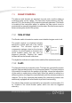
DA20-100 ‘Katana’ 4X Manual DESCRIPTION 7.3.3 FLAP POSITION INDICATOR The current flap position is indicated by three control lights beside the flap operating switch. FLAPS POSITION CRUISE T/O LDG Light green yellow yellow Degree 0° 15° 40° Flaps When two lights are illuminated at the same time, the flaps are between these two positions. This is the case while the flaps are in motion. 7.3.4 PEDAL ADJUSTMENT ! NOTE: The pedals may only be adjusted on the ground.
DA20-100 ‘Katana’ 4X Manual DESCRIPTION 7.3.5 FLIGHT CONTROL LOCK A flight control lock, P/N 20-1000-01-00 , is provided with each aircraft and should be installed whenever the aircraft is parked. ! ! NOTE: Failure to install the flight control lock whenever the aircraft is parked may result in control system damage, due to gusts or turbulence. FSX: The Flight Control Lock (red band) is stored in the baggage compartment if not applied to the controls and can be used by a click with the mouse.
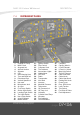
DA20-100 ‘Katana’ 4X Manual 7.4. DESCRIPTION INSTRUMENT PANEL 31 24 41 1 2 23 27 6 43 36 28 10 7 35 38 29 8 40 37 11 9 39 13 30 12 21 13 33 32 34 5 4 3 26 42 16 17 14 15 18 19 20 22 47 49 50 48 56 51 52 53 56 55 54 45 44 1. 2. 3. 4. 5. 6. 7. 8. 9. 10. 11. 12. 13. 14. 15. 16. 17. 18. 19. 20. Outside Air Temp. M803 Clock Airspeed Ind. Artifical Horizon Altimeter CDI Stall Warning Horn Turn and Bank Ind. Directional Gyro Vertical Speed Ind.
DA20-100 ‘Katana’ 4X Manual DESCRIPTION 7.4.1 FLIGHT INSTRUMENTS The flight instruments are installed on the pilot's side of the instrument panel. 7.4.2 CABIN HEAT The cabin heat and defrost system, directs ram air through the coolant radiator and the heat shroud (located around the muffler) into the heat valve. The warm air is then directed to both the window defrosting vents and to the cabin floor. The cabin heat knob, located in front of the center console, is used to regulate the flow of heated air.
DA20-100 ‘Katana’ 4X Manual DESCRIPTION 7.5.1 WHEEL BRAKES Hydraulically operated disc brakes act on the wheels of the main landing gear. The wheel brakes are operated individually using the toe-brake pedals either on the pilot's or on the co-pilot's side. If either the left or right wheel brake system on the pilot’s side fail, the co-pilot’s brakes fail too. The same applies to a failure on the co-pilot’s side, in this case, also the pilot’s brakes fail.
DA20-100 ‘Katana’ 4X Manual 7.6. DESCRIPTION SEATS AND SAFETY BELTS The seats are removable to facilitate the maintenance and inspection of the underlying controls. Covers on the control sticks prevent loose objects to foul the controls. The seats are equipped with removable cushions. Manually triggered seattype parachutes may be used instead of cushions. For automatically triggered parachutes it is possible to install suitable fastening loops on the A-bolts (under the seats).
DA20-100 ‘Katana’ 4X Manual 7.8. DESCRIPTION CANOPY The canopy is closed by pulling down on the forward handles on the canopy frame. Locking the canopy is accomplished by pushing forward on the two locking handles on the left and right side of the frame. To lock: Push both LH and RH locking handles forward. To unlock: Pull both LH and RH locking handles backwards.
DA20-100 ‘Katana’ 4X Manual 7.9. DESCRIPTION POWERPLANT 7.9.1 ENGINE Rotax 912, 4 cylinder, 4 stroke engine, horizontally opposed, liquid cooled cylinder heads, air cooled cylinders. Propeller drive via integrated reduction gear (crankshaft RPM in parentheses). Displacement: Max. T/O Power (5 min.): Max. Continuous Power: 1.352 litres (82.5 cu.in.) 100 HP / 73.5 kW at 2385 RPM (5800 RPM 94 HP / 69 kW at 2260 RPM (5500 RPM) Additional information can be found in the Engine Operating Manual.
DA20-100 ‘Katana’ 4X Manual Carburetor Heat: DESCRIPTION Square knob Knob pulled = ON During normal operation the Carburetor heat is OFF (knob pushed IN) Throttle: Large lever with black conical knobs Lever full forward = FULL throttle Lever full rearward = IDLE Propeller Pitch Control Lever: Lever with blue notched knob, right of throttle Lever forward = max. RPM (fine pitch) Lever rearward = min. RPM (coarse pitch) (also see page 7-10). 7.9.
DA20-100 ‘Katana’ 4X Manual DESCRIPTION 7.9.5 PROPELLER GOVERNOR Woodward A 210786. 7.9.6 PROPELLER PITCH ADJUSTMENT Propeller pitch adjustments are made with the propeller pitch control lever located on the center console (throttle quadrant) to the right of the throttle. Pulling the lever backwards causes a reduction in RPM. The governor keeps the selected RPM constant regardless of airspeed or throttle setting.
DA20-100 ‘Katana’ 4X Manual DESCRIPTION 7.9.7 LUBRICATING The engine is equipped with a dry sump forced flow lubrication system. If the engine is not operated for an extended period of time, it is possible that some of the oil may drain back into the engine, resulting in a false dip stick reading. To check the oil level, remove the oil tank cap and turn the propeller by hand in the normal rotation of operation. This is to transfer all the oil from the engine crankcase to the oil tank.
DA20-100 ‘Katana’ 4X Manual DESCRIPTION 7.10.
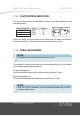
DA20-100 ‘Katana’ 4X Manual DESCRIPTION 7.10.1 FUEL SHUT-OFF VALVE Fuel Valve CLOSED The fuel shut-off valve is located on the left hand side of the center console near the pilot's feet. In the open position the tap is parallel to the direction of flight. The valve is protected against unintentional shutoff by a locking detent. Fuel Valve OPEN Fuel Valve OPEN Fuel Valve CLOSED ! WARNING: The fuel shut-off valve should only be closed during engine fire or fuel system maintenance.
DA20-100 ‘Katana’ 4X Manual DESCRIPTION 7.11. ELECTRICAL SYSTEM Generator Failure 7.11.1 POWER SUPPLY 50 B+ Both circuit breakers can be t r i g g e r e d m a n u a l l y. T h e generator warning light is activated by the voltage regulator monitoring circuit and illuminates when the generator is not charging the battery. Generator Master L G Generator 2 Over voltage Sensor Over voltage Relay Electrical Bus A 12 V battery is connected to the master bus via the master circuit breaker (50 Amps).
DA20-100 ‘Katana’ 4X Manual DESCRIPTION 7.11.3 ELECTRICAL POWERED EQUIPMENT The individual consumers (e.g. Radio, Fuel Pump, Position Lights, etc.) are connected in series with their respective circuit breakers. Equipment that does not have switches installed, and requires a switch, is controlled by rocker switches in the lower left side of the instrument panel. Refer to Section 7.4 for a illustration of the instrument panel. 7.11.
DA20-100 ‘Katana’ 4X Manual DESCRIPTION 7.11.6 GENERATOR WARNING LIGHT The generator warning light (red) illuminates during Generator failure: no output from the generator. GEN FUEL The only remaining power source is the battery (20 amps. for 30 minutes) 7.11.7 FUEL PRESSURE INDICATOR As soon as the fuel pressure drops below 1.45 psi (0.1 bar), the fuel pressure switch closes, and the fuel pressure warning light illuminates. GEN FUEL 7.11.
DA20-100 ‘Katana’ 4X Manual DESCRIPTION 7.12. PITOT AND STATIC PRESSURE SYSTEMS The pitot pressure is measured on the leading edge of a calibrated probe below the left wing. The static pressure is measured by the same probe using two holes in the lower edge and rear edge of the probe. For protection against water and humidity, water sumps are installed within the line. These water sumps are accessible beneath the left seat shell.