
Systems Guide


A318/A319/A320/A321
Professional
SYSTEMS
Systems guide
Vol
4
04-03-9
11 July 2018
electrically operated inlet flap and the exhaust vents in the tail cone. The electrical starter will start the
engine when the inlet flap is fully opened. The fuel is taken from the left-wing tank using a separate fuel
pump.
AIR BLEED SYSTEM
Bleed air from the APU is selectable from the overhead panel and has priority over main engine bleed air
if the APU BLEED pb is ON. The bleed air can start engines and provide the air condition system.
CONTROLS AND DISPLAYS
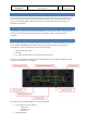
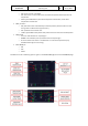
The APU ECAM page displays the parameters of the APU. For the gas turbine engine N (in %) and EGT (in
°C) are available. The APU generator shows load (in %), voltage (in V) and frequency (in HZ) plus the
connection to the bus (arrow when connected, nothing when not connected). Bleed air shows pressure
(in PSI) plus the position of the valve (open or closed). All system messages are shown in green while
within correct parameters, or amber when outside correct parameters.
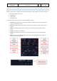
The APU MASTER SW pb on the overhead APU panel is pressed (ON will show) to power up the APU
computer, the fuel pump is activated, and the air inlet is opened. When ON is shown the APU is ready to
start.
The APU START pb starts the APU. When pressed it will show ON and the APU computer will command
and control the startup. Aircraft batteries must be selected ON, even when the engine generators are
online. When the APU is running and bleed air and electrical power are available a green AVAIL will show,
and the ON will not be shown. Note the APU needs a 3-minute cool down period after it has shut down.
On the ELEC panel the APU GEN pb will be dark when the APU generator is ON, and when pressed it will
show OFF as the APU generator is taken of line. When there is any problem an amber FAULT will show
and the ECAM will show more information.
On the AIR COND panel, the APU BLEED pb will show ON when APU N speed is sufficient. When pushed
the pb will be dark and the bleed air valve will close. When there is any problem an amber FAULT will
show and the ECAM will show more information.
AUTOFLIGHT
OVERVIEW
The following components are used by the pilot to interact with the autoflight system:
• Flight Control Unit (FCU)
• Multifunction Control and Display Units (MCDUs)
• Sidesticks
• Thrust levers
• Primary Flight Display (PFD)
• Navigation Display (ND)