
Systems Guide

A318/A319/A320/A321
Professional
SYSTEMS
Systems guide
Vol
4
04-03-36
11 July 2018
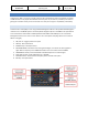
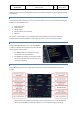
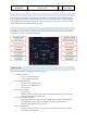
• The TR indications (TR 1 & TR 2) display in green when the values are within normal limits and in
amber when these are exceeded. Output voltage (V) and amperage (A) are shown.
• The generator indications (GEN 1 & GEN 2) show the load (%), voltage (V) and frequency (HZ)
normally in green, for any abnormal value the same is shown in amber. Connection lines will
show if the generator is online.
• The External Power indication will show voltage (V) and frequency (HZ) and connecting lines but
only when external power is available.
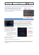
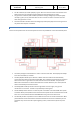
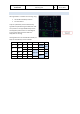
ELEC OVERHEAD PANEL
All the normal operations for the electrical system are done via pushbuttons on the overhead ELEC panel.
• The battery voltage for both batteries is shown in the two small LCDs. These displays will always
be on when the battery is installed.
• The BAT pbs (BAT 1 & BAT 2) are off when in AUTO mode. The batteries will automatically
connect when the APU is started without EXT PWR, when voltage drops below 26.5 (to charge) or
when the aircraft is on ground and no other electrical sources are available. They will show
FAULT when the batteries are disconnected because of a fault. When the pb is clicked, OFF will
show and the battery will be disconnected.
• The IDG pb (IDG 1 & IDG 2) will disconnect the generator from the engine, only ground
maintenance can reset this. The switch is protected by a switch guard.
• The EXT PWR pb will be off when no external power is available. It will show AVAIL when power
is available. When pushed, ON will show and the external power will be connected to the aircraft
buses. It is recommended to deselect EXT PWR before the ground crew disconnects.
• The ACC ESS pb makes it possible to select a different source for the aircraft essential bus. When
pushed ALTN will show and AC2 will be selected instead of AC1.Commercial and Galley are not
simulated. They connect the cabin systems (galleys, toilets, entertainment system etc) to the
buses.