Volume 4: Systems Record of revisions revision n° 001 Issue date Release Description 15 June, 2018 1.00 completion 002 10 July, 2018 1.
A318/A319/A320/A321 Professional SYSTEMS Systems guide Vol 4 04-03-2 11 July 2018 CONTENTS INTRODUCTION .............................................................................................................................................. 5 AIRCRAFT GENERAL ........................................................................................................................................ 5 AIR CONDITIONING & PNEUMATICS .........................................................................
A318/A319/A320/A321 Professional SYSTEMS Systems guide Vol 4 04-03-3 11 July 2018 SELECTED SPEED ...................................................................................................................................26 MANAGED LATERAL GUIDANCE............................................................................................................27 SELECTED LATERAL GUIDANCE HEADING OR TRACK ............................................................................27 MANAGED CLIMB.......
A318/A319/A320/A321 Professional SYSTEMS Systems guide Vol 4 04-03-4 11 July 2018 FUEL FEED SEQUENCE ...........................................................................................................................48 CENTRE FUEL TANK TRANSFER .............................................................................................................48 OVERHEAD PANEL ................................................................................................................................
A318/A319/A320/A321 Professional SYSTEMS Systems guide Vol 4 04-03-5 11 July 2018 INTRODUCTION It is very easy to find actual manuals for the A320 range of aircraft on the internet. For obvious reasons we cannot include them but even a quick search will lead you to a treasure-trove of information. Start your search with ‘A320 FCOM’ to find complete operation manuals. Almost all you find in there are applicable to this product.
A318/A319/A320/A321 Professional SYSTEMS Systems guide Vol 4 04-03-6 11 July 2018 o o • • • ON: hot air pressure is regulated OFF: valve closes + trim air valve closes, and cabin temperature will drop to external temperature o FAULT: (plus ECAM caution) when duct temperature is above 80°C, resets when temperature is below 70°C PACK pb switch o ON: pack flow control is automatically controlled (note the pack flow valve is closed during certain conditions like engine start etc.
A318/A319/A320/A321 Professional SYSTEMS Systems guide Vol 4 04-03-7 11 July 2018 PRESSURIZATION Under normal operation conditions the complete pressurization is fully automatic. The system consists of: • • • • two Cabin Pressure Controllers outflow valve control panel two safety valves In automatic operation pressurization is divided in 6 different modes • • • • • • Ground: before take-off and 1 minute after landing the outflow, valve is fully open to equalize pressure with outside pressure.
A318/A319/A320/A321 Professional SYSTEMS Systems guide Vol 4 04-03-8 11 July 2018 VENTILATION The ventilation of avionics is controlled by the Avionics Equipment Ventilation Controller (AEVC). It provides cooling of the avionics compartments using two fans, a heat exchanger that uses the outside skin of the aircraft to cool the air and an inlet and outlet valve. Only the automated mode is simulated, and you can see the ventilation valve position on the CAB PRESS ECAM page.
A318/A319/A320/A321 Professional SYSTEMS Systems guide Vol 4 04-03-9 11 July 2018 electrically operated inlet flap and the exhaust vents in the tail cone. The electrical starter will start the engine when the inlet flap is fully opened. The fuel is taken from the left-wing tank using a separate fuel pump. AIR BLEED SYSTEM Bleed air from the APU is selectable from the overhead panel and has priority over main engine bleed air if the APU BLEED pb is ON.
A318/A319/A320/A321 Professional SYSTEMS Systems guide Vol 4 04-03-10 11 July 2018 The autoflight system is part of the Flight Management System (FMS). The FMS (including autopilots and autothrust system) is made up by two Flight Management Guidance Computers (FMGCs) and two Flight Augmentation Computers (FACs). FACs FMGCs • • • FMS FLIGHT MANAGEMENT FLIGHT GUIDANCE FLIGHT AUGMENTATION Flight Management provides navigation, performance optimization and display management.
A318/A319/A320/A321 Professional o SYSTEMS Systems guide Vol 4 04-03-11 11 July 2018 In managed mode the displays are dashed (note the FCU altitude windows is never dashed) and the control of speed and lateral/vertical navigation is managed by the FMS. MULTIFUNCTION CONTROL AND DISPLAY UNIT The MCDUs is the primary interface between pilot and FMS (and in our simulation it is also used to access some simulation functions.
A318/A319/A320/A321 Professional SYSTEMS Systems guide Vol 4 04-03-12 11 July 2018 FLIGHT PHASES The FMGC divides the complete flight into phases that normally will automatically switch to the next phase when certain conditions are met.
A318/A319/A320/A321 Professional • • • SYSTEMS Systems guide Vol 4 04-03-13 11 July 2018 The autopilot is automatically disengaged when the throttles are set above FLX/MCT on ground. The autopilot is automatically disengaged when a normal law is exceeded, or pitch or bank angle are excessive. The autopilot is automatically disengaged during a non-precision approach when the aircraft reaches MDA minus 50 feet.
A318/A319/A320/A321 Professional SYSTEMS Systems guide Vol 4 04-03-14 11 July 2018 AUTOTHRUST MODES FIXED THRUST MODES • • • • • • TOGO: Provides fixed maximum thrust and is only available when autothrust status is armed. FLX: Flex thrust is used for reduced thrust takeoffs. Thrust is calculated using the assumed temperature as set in the MCDU. MCT: Provides Maximum Continuous Thrust at the current ambient conditions.
A318/A319/A320/A321 Professional SYSTEMS Systems guide Vol 4 04-03-15 11 July 2018 ALPHA FLOOR The alpha floor protection assists the pilot in recovering from dangerous low speed and high angle of attack by automatically setting TOGA thrust when: • • • Excessive angle of attack (alpha) Excessive high nose up attitude Windshear is detected When the alpha floor conditions are no longer detected the autothrust system will stay in TOGA lock until the pilot disables auto throttle.
A318/A319/A320/A321 Professional SYSTEMS Systems guide Vol 4 04-03-16 11 July 2018 FLIGHT GUIDANCE Flight guidance is provided for speed control, lateral navigation and (limited in this project) vertical navigation. There are two types: • • Selected Guidance: In this mode the aircraft will fly on autopilot using the settings on the FCU. You switch from managed mode to selected mode by pulling (right mouse click) the SPD, HDG and ALT knobs.
A318/A319/A320/A321 Professional SYSTEMS Systems guide Vol 4 04-03-17 11 July 2018 VERTICAL MODES The vertical guidance modes will make the aircraft change altitude.
A318/A319/A320/A321 Professional • • SYSTEMS Systems guide Vol 4 04-03-18 11 July 2018 CLB mode is automatically selected when o ACC ALT is reached o ALT CSTR is reached with CLB mode armed CLB mode can be manually selected by pushing the ALT selector knob.
A318/A319/A320/A321 Professional SYSTEMS Systems guide Vol 4 04-03-19 11 July 2018 DESCENT DES mode provides vertical guidance following a computed descent profile between Top of Descent to the Deceleration point. It uses the data in the F-PLN and the available WIND data.
A318/A319/A320/A321 Professional SYSTEMS Systems guide Vol 4 04-03-20 11 July 2018 GUIDANCE In DES mode the aircraft is guided along the DES PATH. The SPD target can be selected or managed (with the speed to vary around the calculated optimal nominal descent speed. SPD CSTR is considered in the speed profile. If the aircraft is above the DES PATH it will pitch down until the upper limit of the MANAGED SPD RANGE is reached. That speed will be kept, and the aircraft will differentiate from the DES PATH.
A318/A319/A320/A321 Professional SYSTEMS Systems guide Vol 4 04-03-21 11 July 2018 GUIDANCE In the ALT* and ALT CST* mode the vertical speed is managed to reduce vertical speed to ensure a smooth capture of the set FCU altitude. ALTITUDE HOLD ALT mode will keep the aircraft at a set altitude. The altitude can be a FCU set altitude (with ALT engaged) or an altitude constraint. ARMING CONDITIONS • ALT mode is automatically armed when the aircraft climbs or descents to a target altitude.
A318/A319/A320/A321 Professional SYSTEMS Systems guide Vol 4 04-03-22 11 July 2018 DISENGAGEMENT CONDITIONS • Engagement of other vertical mode o Manually by pulling altitude selection knob or performing a go around o Automatically by reaching FCU altitude or G/S* engagement GUIDANCE FMGS pitch mode will guide the aircraft to the target V/S (FPA). A/THR mode is SPD or MACH. V/S-FPA guidance has priority over speed guidance and when reaching the limit of the flight envelope will change to OPEN mode.
A318/A319/A320/A321 Professional SYSTEMS Systems guide Vol 4 04-03-23 11 July 2018 The RUNWAY mode will provide lateral guidance during takeoff and immediately thereafter using the LOC signal (when it is available. The RUNWAY TRK mode will provide lateral guidance on an extended runway center line.
A318/A319/A320/A321 Professional SYSTEMS Systems guide Vol 4 04-03-24 11 July 2018 DISENGAGEMENT CONDITIONS • • • • • Depressing the APPR pb (both LOC and G/S mode will disarm) Depressing the LOC pb (only G/S will disarm) Pull action on the V/S/FPA button Pull action on the HDG/TRK button Go AROUND mode selected LAND MODE LAND mode engages automatically when the LOC and G/S modes are engaged, and aircraft is below 400 AGL. FLARE MODE At 40 ft RA the FLARE mode automatically engages.
A318/A319/A320/A321 Professional SYSTEMS Systems guide Vol 4 04-03-25 11 July 2018 ENGAGEMENT CONDITIONS • • • • Radio Altimeter active APP phase is active APP NAV mode engaged FINAL is armed DISENGAGEMENT CONDITIONS • • • • Depressing the APPR pb Depressing the LOC pb Automatically at MDA (MDH) Go AROUND mode selected GUIDANCE The aircraft is guide down to MDA/MDH where AP is automatically disconnected. GO AROUND This mode is a combination of the SRS vertical and the GA TRK lateral mode.
A318/A319/A320/A321 Professional SYSTEMS Systems guide Vol 4 04-03-26 11 July 2018 MANAGED MODE VERSUS SELECTED MODE In Managed mode the Flight Management Guidance Computer sends information to the Autopilot systems so that it follows the programmed route. This route can include headings, altitudes and even speeds. The pilot selects this mode by pushing (left click) the appropriate selector knob on the Flight Control Unit (FCU).
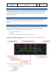
A318/A319/A320/A321 Professional SYSTEMS Systems guide Vol 4 04-03-27 11 July 2018 MANAGED LATERAL GUIDANCE • • • • On the PFD the FMA will display NAV On the FCU the Heading/Track window will show dashes and a white dot On the PFD/ND the actual (not selected) heading and actual track is displayed On the ND the flight plan track is displayed as a continuous green line SELECTED LATERAL GUIDANCE HEADING OR TRACK • • • • On the PFD the FMA will display HDG (or TRK) On the PFD/ND the selected heading or
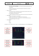
A318/A319/A320/A321 Professional SYSTEMS Systems guide Vol 4 04-03-28 11 July 2018 MANAGED CLIMB • • • On the PFD the FMA will display a green CLB, with a blue ALT beneath it On the FCU the altitude will show the dialed value with a white dot to the right of it On the MCDU (PERF page) will be displayed as the CLB page OPEN CLIMB • • • To activate OP CLB, pull (right click) the FCU ALT knob after dialing in a higher altitude.
A318/A319/A320/A321 Professional SYSTEMS Systems guide Vol 4 04-03-29 11 July 2018 SELECTED CLIMB • • • For selected V/S climb, pull (right click) the FCU V/S knob. On the PFD the FMA will show in green VS and in blue the selected vertical speed, with a blue ALT beneath it. On the FCU you will read the selected V/S with a + sign to the left of it, and the dialed altitude without a white dot to the right of it.
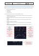
A318/A319/A320/A321 Professional SYSTEMS Systems guide Vol 4 04-03-30 11 July 2018 OPEN DESCENT • • • To activate OP DES pull (right click) the FCU ALT knob after dialing in a lower altitude. OP DES acts like OP CLB, in that it will descend in an idle descent to the altitude dialed in the FCU disregarding any altitude constraints.
A318/A319/A320/A321 Professional SYSTEMS Systems guide Vol 4 04-03-31 11 July 2018 VERTICAL GUIDANCE LE VEL OFF • • • To immediately level off, push (left click) the FCU V/S knob. On the PFD the FMA will show in green VS and in blue 0, with a blue ALT beneath it.
A318/A319/A320/A321 Professional SYSTEMS Systems guide Vol 4 04-03-32 11 July 2018 COMMUNICATIONS Unfortunately, P3D is not very strong with radios and we really wanted to stick to the default commands of P3D because a lot of people have hardware for these parts. So, we went for practicality more than for getting the simulation exactly as the real aircraft. It’s a small price to pay for compatibility and usability.
A318/A319/A320/A321 Professional SYSTEMS Systems guide Vol 4 04-03-33 11 July 2018 AUDIO MANAGEMENT SYSTEM The Audio Management System determines which sources you will hear. With the button depressed the source is not heard, with the button depressed and lit the corresponding source is heard. Please note that P3D does not have a separate ILS receiver and that is always linked to VOR 1.
A318/A319/A320/A321 Professional SYSTEMS Systems guide Vol 4 04-03-34 11 July 2018 The windshields consist of multi layered glass and are electrically heated to prevent icing. Two of the windows have sliding mechanisms. To open the windows left mouse click on the handle. The window will be opened by a rattle mechanism. To close the window, right mouse click on the handle. Make sure the red ring underneath the release button is shown to indicate the window is locked.
A318/A319/A320/A321 Professional SYSTEMS Systems guide Vol 4 04-03-35 11 July 2018 advised to either connect external power of power up the APU to avoid your aircraft going cold and dead unexpectedly. PRIORITY LOGIC The priority logic determines which source is used. When that source is lost the system will automatically switch to the next available source. 1. 2. 3. 4. 5.
A318/A319/A320/A321 Professional • • • SYSTEMS Systems guide Vol 4 04-03-36 11 July 2018 The TR indications (TR 1 & TR 2) display in green when the values are within normal limits and in amber when these are exceeded. Output voltage (V) and amperage (A) are shown. The generator indications (GEN 1 & GEN 2) show the load (%), voltage (V) and frequency (HZ) normally in green, for any abnormal value the same is shown in amber. Connection lines will show if the generator is online.
A318/A319/A320/A321 Professional • • • SYSTEMS Systems guide Vol 4 04-03-37 11 July 2018 The GEN pbs (GEN 1 & GEN 2) are dark in AUTO mode. FAULT will show when the generator is inoperative, or the engine is not running. When pushed OFF will show and the generator will be disconnected from the AC bus. The APU GEN pb is normally in the ON position (lights off) and the generator will be available when the APU is running. When there is a problem FAULT will show.
A318/A319/A320/A321 Professional SYSTEMS Systems guide Vol 4 04-03-38 11 July 2018 COMPUTERS There seven flight control computers that process the pilot inputs: • • • 2 ELAC’s (Elevator Aileron Computer) 3 SEC’s (Spoiler Elevator Computer) 2 FAC’s (Flight Augmentation Computer) PITCH CONTROL The two elevators and THS control pitch. The pitch is normally controlled by ELAC 2 and uses the green and yellow hydraulic systems. The THS uses three electrical motors.
A318/A319/A320/A321 Professional SYSTEMS Systems guide Vol 4 04-03-39 11 July 2018 OVERHEAD PANEL CONTROLS There are two FLT CTL panels on the overhead panel. When the corresponding system is ON and without fault the pb will be dark. When clicked OFF will show and the corresponding computer will be deactivated. When clicked again the computer will reset and restart. The two panels are mixed, so each crew member will be able to control at least one ELAC, SEC and FAC.
A318/A319/A320/A321 Professional Vol 4 SYSTEMS Systems guide FLAPS AND SLATS Lift augmentation is achieved on each wing using: • • Two double-slotted flap surfaces Five slat surfaces They are hydraulically moved and electrically signaled and operated using the FLAPS lever that has 5 positions. The upper ECAM always shows the flaps/slats position both in a small diagram and in position (with animation when the flaps/slats are moving).
A318/A319/A320/A321 Professional SYSTEMS Systems guide Vol 4 04-03-41 11 July 2018 FLIGHT INSTRUMENTS The flight instruments consist of the Electronic Instrument System (EIS) and several additional instruments. The EIS has six identical displays and is made up of two subsystems, the Electronics Flight Instrument System (EFIS) and the Centralized Aircraft Monitor System (ECAM).
A318/A319/A320/A321 Professional SYSTEMS Systems guide Vol 4 04-03-42 11 July 2018 The colors on the EFIS show the importance of the information shown: • • • • • • RED: Failure requiring immediate action AMBER: Failure requiring action GREEN: Shows FMCG and NDB navigation information, flight director and engaged flight guidance modes WHITE: Used for titles, scales and VOR information BLUE: Used for armed flight modes, VOR, CDI and tuned navaids MAGENTA: Used for ILS navaids information.
A318/A319/A320/A321 Professional SYSTEMS Systems guide Vol 4 04-03-43 11 July 2018 When neither caution nor warnings are present the page shown is controlled by flight phase. • • • • On the ground and engines off -> Doors page On the ground and engines on -> Wheels page Take-off run and until reaching 1500 ft AGL -> Engines page Above 1500 AGL -> Cruise page If a caution or warning is triggered the ECAM will show the page for the affected system and CLR button will be lit.
A318/A319/A320/A321 Professional Vol 4 SYSTEMS Systems guide 04-03-44 11 July 2018 CLOCK The clock provides time related information • • • CHR: chronometer, start and stop with the CHR button, reset with the RST button UTC: shows UTC time ET: shows flight time (triggered by flight mode START) VOR/DME RECEIVERS There are two VOR/DME receivers and the information is supplied on the Navigation Display (ND).
A318/A319/A320/A321 Professional SYSTEMS Systems guide Vol 4 TOGA LK A/THR active and TOGA thrust locked (not in alpha FLOOR condition) Flashing White Flashing White LVR ASYM Set the thrust levers in CL detent Set the thrust levers in MCT/FLEX DETENT Only one thrust lever is in CL or MCT/FLX detent AP/FD VERTICAL MODE ANNUNCIATIONS SRS CLB OP CLB ALT * ALT CSTR * ALT ALT CSTR ALT CRZ DES OP DES G/S * G/S V/S FPA Takeoff or go around mode engaged Climb mode engaged, FMGS target above, ALT CSTR used
A318/A319/A320/A321 Professional SYSTEMS Systems guide Vol 4 AP/FD A/THR ENGAGEMENT ANNUNCIATIONS RWY HDG NAV LOC * LOC APP NAV RWY mode engaged HDG mode engaged NAV mode engaged LOC capture mode engaged LOC track mode engaged NAV mode engaged for non ILS approach NAV LOC APP NAV NAV mode armed LOC mode armed NAV mode armed for non ILS approach LAND FLARE ROLL OUT FINAL APP LAND mode engaged below 400 feet RA FLARE mode engaged ROLL OUT mode engaged APP NAV and FINAL APP mode engaged during RNAV ap
A318/A319/A320/A321 Professional SYSTEMS Systems guide Vol 4 04-03-47 11 July 2018 APPROACH CAPABILITIES ANNUNCIATIONS AP 1+2 AP 1 AP 2 Autopilot 1 and 2 engaged (LOC/GS, Roll-out or Go-around mode armed or engaged Autopilot 1 engaged Autopilot 2 engaged XFDY 1FD2 indicates FD is activated on both PFD -FD- indicates FD is not activated on both PFD A/THR is activated by: - Setting thrust levers between CL and IDLE, assuming previously armed - Setting thrust levers between MCT and IDLE, assuming prev
A318/A319/A320/A321 Professional WEIGHT SYSTEMS Systems guide 2 X 6048 KG 2 X 13,140 LB 6437 KG 14,190 LB Vol 4 04-03-48 11 July 2018 18605 KG 41,010 LB ENGINE FEED The main fuel pumps feed fuel from the wing tanks to the engines using two fuel pumps in each wing tank. MAIN COMPONENTS • • • • Tank pumps, two in each wing tank, normally both activated. Cross feed valve, allows the left and right systems to be connected and to feed both engines from one wing tank, normally closed.
A318/A319/A320/A321 Professional SYSTEMS Systems guide Vol 4 04-03-49 11 July 2018 OVERHEAD PANEL TK PUMPS (push button switch), pump the fuel from the wing tanks to the engines.
A318/A319/A320/A321 Professional SYSTEMS Systems guide Vol 4 04-03-50 11 July 2018 The ECAM FUEL page is opened by depressing the ECAM FUEL button. This page is automatically opened if any of the fuel systems is abnormal. HYDRAULIC SYSTEM GENERAL There are three separate and fully independent hydraulic systems, Green, Blue and Yellow, each with its own pump(s), reservoir and accumulator. In normal operation the system is fully automated and does not need any interaction.
A318/A319/A320/A321 Professional SYSTEMS Systems guide Vol 4 04-03-51 11 July 2018 ECAM HYD PAGE All pumps are indicated by triangles on the ECAM. When the pump is off it is a white open triangle, when the pump is ON and pressure is normal a green triangle is shown. An amber triangle means the pump is on but pressure too low. HYD OVERHEAD PANEL The Hydraulic panel on the overhead panel allows the crew to interact with the system in case of failures.
A318/A319/A320/A321 Professional SYSTEMS Systems guide Vol 4 04-03-52 11 July 2018 ICE AND RAIN PROTECTION Using the ice and rain protection systems allow the unrestricted use of the aircraft in severe icing conditions and heavy rain fall. Electrical heating is provided for flight compartment windows, probes, pitot tubes, static ports and waste water drains (though the latter is not simulated).
A318/A319/A320/A321 Professional SYSTEMS Systems guide Vol 4 04-03-53 11 July 2018 Both front windshields have individual windshield wipers controlled by three position switches on the overhead panel. Activating them on a dry windshield might cause damage to the windshield. Using the wipers at airspeed over 240 knots is not advised and not really needed. LANDING GEAR AND BRAKES GENERAL The landing gear consists of a steerable nose gear with two wheels and two main landing gear with two wheels.
A318/A319/A320/A321 Professional SYSTEMS Systems guide Vol 4 04-03-54 11 July 2018 MAIN WHEEL BRAKES The brakes are operated by the brake pedals or the autobrake system via the Green hydraulic system. Temperature sensors in each main wheel display the temperature on the ECAM WHEELS page. Takeoff is not allowed before the brakes are below 300°C. ANTI-SKID The anti-skid system operates when wheel skid is detected and will provide maximum brake efficiency.
A318/A319/A320/A321 Professional SYSTEMS Systems guide Vol 4 04-03-55 11 July 2018 PARKING BRAKE The parking brake is commanded with the PARK BRK handle. Verify the parking brake is on by checking the ACCU-PRESS gauge. Normally the aircraft is not parked with the parking brakes applied, but with chocks to keep it in place. However, during icing conditions, refueling or with high winds parking brakes are used.
A318/A319/A320/A321 Professional SYSTEMS Systems guide Vol 4 04-03-56 11 July 2018 MASTER CAUTION, MASTER WARNING & AUTOLAND WARNING The MASTER WARN pb and MASTER CAUT pb alert the pilot to a problem in one of the systems or an unsafe condition. The MASTER WARN pb is accompanied by a continuous chime while the MASTER CAUT pb only sounds a single chime. When pushed the caution and warning system is reset.
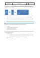
A318/A319/A320/A321 Professional SYSTEMS Systems guide Vol 4 04-03-57 11 July 2018 RADIO NAVIGATION NAVIGATION RADIOS The navigation radios are set in the MCDU on the RADIO NAV page. You enter this page by pressing the RADNAV key. Tuning to a station is as simple as entering the frequency (like 117.50) or the name (like SPA) on the scratchpad and then clicking the button next to the radio you want to tune. If there is more than one station with the same name or frequency the nearest is always selected.
A318/A319/A320/A321 Professional • • • • • • • • • • • • • SYSTEMS Systems guide Vol 4 04-03-58 11 July 2018 Runway End Taxiway Take-off Insufficient Runway Length Extended Holding on Runway Approaching Short Runway (in air) Taxiway Landing Flaps Setting (Take-off and Landing) Landing Distance Remaining Distance Remaining (Rejected Take-off) Excessive Approach Speed Excessive Approach Angle Unstable Approach Altimeter settings (above and below Transition) RADIO ALTIMETER / TCAS Two radio altimeters (o
A318/A319/A320/A321 Professional SYSTEMS Systems guide Vol 4 04-03-59 11 July 2018 POWER PLANT The A320 series are powered by two CFM56 or IAE V2500 turbofan engines. Though these engines have slightly different characteristics, these differences are hard to notice for the crew as they are controlled by FADEC systems. The type rating of an pilot does not even mention the engine type.
A318/A319/A320/A321 Professional SYSTEMS Systems guide Vol 4 04-03-60 11 July 2018 MANUAL MODE The engines are in manual mode when the thrust levers are outside the operating range and the ATS is not activated. In manual mode the pilot operates the engines by moving the thrust levers between idle and T.O./G.A. The FADEC will calculate the optimal N1 rating for each position. When on ground and the thrust levers are in the FLEX detent the FADEC will select a thrust rating based on flex T.
A318/A319/A320/A321 Professional SYSTEMS Systems guide Vol 4 04-03-61 11 July 2018 AUTOTUNE ILS An ILS is autotuned when the departure runway has a ILS (during PREFLIGHT AND TAKE OFF mode) and when the F-PLN approach mode has an ILS in all other modes. PASSENGER SIGNS The passenger (previously no smoking) signs should be left ON during all operational flights. The seatbelt sign behavior is semi-automated when in AUTO and the seatbelts sign will be lit when the aircraft is below 10,000 feet.
A318/A319/A320/A321 Professional SYSTEMS Systems guide Vol 4 04-03-62 11 July 2018 In auto mode (MULTISCAN switch set to AUTO) the tilt is automatically controlled. Two beams (upper and lower) are merged together to become one picture representing weather in the possible vertical flight path of aircraft. Also in MULTISCAN AUTO mode the GCS (ground clutter suspension) is usually in AUTO mode and so the ground clutter will be suppressed.
A318/A319/A320/A321 Professional Vol 4 SYSTEMS Systems guide 04-03-63 11 July 2018 The recommended TILT settings for the various FLIGHT PHASES based on ALTITUDE and ND-RANGE according to documentation (Flight Operations Briefing Notes) are: Flight Phase Taxi Recommendations Remarks Set ND to 10 NM range – Tilt down, then up: Check appearance / disappearance of ground returns Radar check must be performed away from people Scan along the departure path Change TILT according to altitude and ND range T
A318/A319/A320/A321 Professional SYSTEMS Systems guide Vol 4 04-03-64 11 July 2018 CONTROLS The following features are modeled respectively can be operated in the Aerosoft A318/319/A320/A321: • • • • • GAIN (-15<>+15): Sets the sensitivity of the receiver. MULTISCAN (MAN and AUTO): Multiscan mode is in Auto, off in Man. GCS (OFF and AUTO): Ground Clutter Suppression. TILT ( -15° <> +15°): Controls the pitch of the radar transmitter.
A318/A319/A320/A321 Professional SYSTEMS Systems guide Vol 4 04-03-65 11 July 2018 Creating a mental image of the weather using the weather radar is a complex task where experience is very important. Areas to avoid are large areas with heavy rain or smaller areas with tight color bands meaning there is only a small area where the rain increases in density. Keep in mind that strong fronts hide whatever is behind them.
A318/A319/A320/A321 Professional SYSTEMS Systems guide GLOSSARY ABV ADF A/C AGL A.
A318/A319/A320/A321 Professional GPU GPWS GS GW HDG hPa IAE ILS In Hg INIT KG IRS L/G LK LOC LSK MCDU MDA MKR N/W ND NDB (ADF) NM PB PERF PFD PPU PROG QNH PSI PTU RAD/NV RAAS RMP RTO RWY SD SEC SID SRS STAR STDBY SW TA TA/RA TAS T/C TCAS T/D TERR THR THR RED THRT THS TOGA TOW TRANS SYSTEMS Systems guide Ground Power Unit Ground Proximity Warning System Glide Slope Gross Weight Heading Air Pressure Unit of Measurement (hector Pascal) Int.
A318/A319/A320/A321 Professional TRK UTC V1 V2 V/S Vfe VHF Vls Vmax Vmo/Mmo VOR Vr XFR ZFW ZFWCG SYSTEMS Systems guide Track Universal Coordinated Time Speed at which takeoff cannot be aborted Minimum Takeoff Safety Speed Vertical Speed Maximum Flap Extended Speed Very High Frequency Minimum Safe Speed Maximum Operating Speed In Current Condition Maximum Operating Limit Speed Very High Frequency Omnirange Station Rotation Speed Transfer Zero Fuel Weight Zero Fuel Weight Centre of Gravity Vol 4 04-03-68