
Step by Step Guide


A318/319/320/321
Profesional
Step-By-Step Tutorial
Vol
6
06-01- 55
11. Dezember 2018
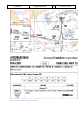
MCDU – PERF – APPR page (A319 and A320)
164.
QNH; TEMP; MAG WIND: Enter data (for arrival airport EGLL)
165.
TRANSITION LEVEL: (TRANS FL) for EGLL = FL070 (In real life determined by ATC, we will use Transition
Altitude plus 1000ft here which would be the correct TL for our weather conditions)
166.
BARO – DA (decision altitude): According to the chart for EGLL ILS27L it is a CAT1 ILS approach. Do
not get confused by the CAT 3 FMA on the PFD. This FMA only tells you what the airplane is capable
of, not what the airport is offering. You can only fly a CAT 3 approach if both the FMA says CAT3 and
the airport has a CAT3 ILS.
So as we are flying an ILS CAT1 landing at EGLL we must enter a Barometric-altimeter DA (decision
altitude). Barometric-altimeter MDA/DA is used for NPA, RNAV as well as ILS CAT1 whereas RADIO-
altimeter DH (decision height) is used for ILS CAT2 and 3 landings. If there is no manual input a
standard BARO value of 200 will automatically be entered by the Copilot. But as the actual BARO-DA
value for our arrival airport EGLL (Heathrow) Runway 27L and ILS approach is according to the charts
= 280 please enter this value.
The information about the available ILS CAT you can get from the charts. The category certification
entails a lot of things. The most important one for CAT2 and CAT3 is a monitoring of the validity of
the ILS signal and a backup power source. For charts there are a few different formats available but
on every ILS chart you will see the capability of the ILS by looking at the minimums. In LIDO charts it
is even spelled out CAT 1, Cat 2 etc. On Jeppesen/AIP charts you sometimes have an extra ILS CAT2/3
charts besides the ILS CAT 1 chart.
167.
VAPP: It is the final approach speed. Unlike with other manufacturers (like Boeing) you do not need
to apply any wind correction here. The “groundspeed mini function” (GS mini) has been
implemented by , but it does not change VAPP, instead, it increases the target (bug) speed when the
headwind is greater than the expected landing headwind - the wind that VAPP was based on. This is
done in case the greater headwind disappeared all at once (wind shear), the airplane would be at
VAPP not VAPP minus the loss of wind. The speed bug moves in response to the wind. For more
information on “GS mini” look at http://www.pprune.org/archive/index.php/t-408276.html.
168.
LDG CONF: (Landing Flap Configuration) If no value is entered manually it defaults to FULL.
Using CONF 3 would provide a decreased fuel burn (due to lower drag) at the expensive of an increased
landing speed, distance and brake wear and a decreased tail clearance due to a higher pitch on landing.
Please use CONF FULL for this tutorial.
5.18 Descent Preparation
DESCENT PREPARATION
NO.
PANEL
ACTION
REMARK
TYP
PART (Name)
PART (No.)
PF (PILOT FLYING)
PM (PILOT MONITORING)
220
1 min after CRZ level has been reached
Start Checklist / Co-Pilot - if selected
221
SEAT BELTS = ON or AUTO
CHECK and set to ON
Cop
222
OVERHEAD
ANTI-ICE
8
ANTI ICE = OFF
CHECK
223
PEDESTAL
RADIO
1
LANDING INFORMATION
RECEIVED
If ATC is used
224
EFIS
A.PRESSURE
2
BARO REF = STANDARD
CHECK
Cop
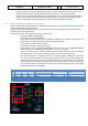
225
MCDU
PERF
APPR
AIR PRESSURE ARRIVAL AIRPORT
“Checked” and readout
Cop
QNH= 1013
226
MCDU
PERF
APPR
DECISION ALTITUDE
“Checked”
Cop
BARO = 280
227
MCDU
PERF
APPR
LDG CONF (Flaps)
"Checked"
CoP
Checklist complete
228
PEDESTAL
XPDR
TCAS MODE
BLW
CoP
169.
DESCENT PREP. CL: It now can be manually started 1 min after reaching CRZ LVL. 40 NM before T/D
(CRUISE CL still active) – a specific information on the INFOBAR pops up also showing the distance to
the automatic start at 10 NM before the T/D. After the checklist has been finished a message on the
infobar pops up “INITIATE DESCENT”. Initiate descent when the T/D marker on the ND has been
reached.
170.
SEAT BELT SIGN : It is also OK if the switch is set to AUTO
171.
ANTI ICE: Should be OFF but if ANTI ICE is ON it is also accepted – condition then will be confirmed