Volume 6: Step by Step Guide Emanuel Hagen RECORD OF REVISIONS revision Issue date n° 001 15 June, 2018 Release Description 1.00 Completion, shared on forum. 002 31-July, 2018 1.01 Fixing several errors 003 10-Dec, 2018 1.
A318/319/320/321 Profesional Step-By-Step Tutorial Vol 6 06-01- 1 11. Dezember 2018 Table of Content Chapter 1. 1.1 1.2 1.3 2. 2.1. 2.1.1 2.1.2 2.1.3 2.1.4 2.1.5 2.1.6 2.1.7 2.2 2.3 2.4 2.5 3. 3.1 3.2 3.3 3.4 3.5 3.6 3.7 3.8 4. 4.1 4.2 4.3 4.4 4.5 4.6 4.6.1 4.6.2 4.6.3 4.6.4 4.6.5 4.6.6 4.7 4.8 4.9 4.10 4.11 4.12 5. 5.1 5.2 5.3 5.4 5.5 5.6 5.7 5.7.1 5.7.
A318/319/320/321 Profesional 5.8 5.9 5.10 5.11 5.12 5.13 5.14 5.15. 5.16 5.17 5.18 5.19 5.20 5.21 5.22 5.23 5.24 5.25 5.26 6. 7. 7.1 7.2 7.3 7.4 7.5 7.6 7.7 7.8 7.9 7.10 7.11 7.12 7.13 8. 8.1 8.2 8.3 8.4 8.5 8.6 8.7 8.8 8.9 8.10 8.11 9. 9.1 9.2 10. 10.1 10.2 10.3 10.4 10.5 10.6 10.7 10.8 11. 12.
A318/319/320/321 Profesional Step-By-Step Tutorial Vol 6 06-01- 3 11. Dezember 2018 PLEASE NOTE THAT DUE TO LAST MINUTES CHANGES OF THE CHECKLISTS SYSTEM THIS STEP BY STEP GUIDE INCUDES CHECKLISTS THAT ARE NOT FULLY INDENTICAL. ALWAYS FOLLOW THE CHECKLISTS IN THE AIRCRAFT. WE WILL UPDATE THIS MANUAL SOON. 1. 1.
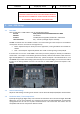
A318/319/320/321 Profesional Step-By-Step Tutorial Vol 6 06-01- 4 11. Dezember 2018 2. Panels and Instruments: In the following paragraph the various panel and cockpit views are explained together with the terms used in the tutorial, this will enable the user to find the knobs, switches and buttons that the tutorial refers to. They are the Glareshield, Main Panel, MCDU, ECAM, Pedestal/Radio and the Overhead Panel.
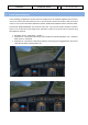
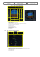
A318/319/320/321 Profesional Step-By-Step Tutorial ECAM and Upper Pedestal view, selected with [F10] Pedestal view, selected with [F11] Overhead view, selected with [F12] Vol 6 06-01- 5 11.
A318/319/320/321 Profesional Vol Step-By-Step Tutorial 06-01- 6 11. Dezember 2018 6 There is also a Panelbar available which allows you to get fast access to a lot of other fixed predefined views – please see chapter 4.6 (OPTIONS). Using the various keyboard combinations (please see details below) all views can be changed • For all views the eye point can be changed except: 2 D Glareshield, 2D MCDU, Radio and TCAS • For all views a "Pan Reset Function" is integrated e. g.
A318/319/320/321 Profesional Vol Step-By-Step Tutorial 2.1.1. 6 06-01- 7 11.
A318/319/320/321 Profesional Indication Step-By-Step Tutorial Vol 6 06-01- 8 11. Dezember 2018 Description Speed Change: Indicates the point where the aircraft will initiate an automatic acceleration or deceleration from current speed to new computed speed in case of SPD LIM, SPD CSTR, or HOLDING SPD (including 250 knots below 10,000). Deceleration Point: Indicates where the aircraft will initiate an automatic deceleration toward VAPP. Managed NAV mode and managed speed must be engaged.
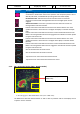
A318/319/320/321 Profesional Vol Step-By-Step Tutorial 6 06-01- 9 11. Dezember 2018 Weather Radar Display • The weather radar display is depicted on the ND in any mode except PLAN. The selected ND range scale will control the weather radar range. • The radar returns will appear in green, yellow and red depending on the precipitation intensity. Black means “no” perception or perception with very low intensity (below level).
A318/319/320/321 Profesional Step-By-Step Tutorial Vol 6 06-01- 10 11. Dezember 2018 • GAIN control • MULTISCAN (MAN and AUTO) • GCS (OFF and AUTO) • Antenna TILT • Mode • Range control of the ND (please see EFIS 2.1.5 #6) Whereas the range control is handled on the EFIS for the other settings the WXR panel is used. To get the maximum range / display it is necessary to have set P3D SETTINGS / WEATHER / CLOUD DRAW DISTANCE to the maximum (if a weather tool is used apply the same settings to it).
A318/319/320/321 Profesional Vol Step-By-Step Tutorial 06-01- 11 11.
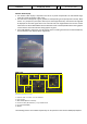
A318/319/320/321 Profesional Step-By-Step Tutorial Vol 6 06-01- 12 11. Dezember 2018 MODE Turbulence is displayed in magenta out to maximal 40 nautical miles for all selected ranges (as in real aircraft). No detecting of clear-air turbulence as only areas of precipitation are evaluated. WX: Normal WX Radar as it was implemented so far (precipitation targets). WX+T: Precipitation targets with turbulence information overlaid. TURB: Only turbulence information without precipitation targets.
A318/319/320/321 Profesional Step-By-Step Tutorial Vol 6 06-01- 13 11. Dezember 2018 The EGPWS is automatically switched in case of a threat but suppressed if the following conditions are met: • Departure: During first 60 seconds after takeoff (after getting airborne). Therefore, the FMA modes for thrust levers (TOGA, FLX, MAN TOGA, MAN MCT) and the SimOnGround flag are taken into account.
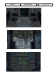
A318/319/320/321 Profesional Vol Step-By-Step Tutorial 6 06-01- 14 11. Dezember 2018 FCU – Flight Control Unit 10 1 2 3 4 5 6 7 8 9 FCU – Flight Control Unit 1 = Speed (display and setting knob) 2 = Heading (display and setting knob) 3 = Altitude (display and setting knob) 4 = Climb / Descent (display/setting knob) 5 = Autopilot 1 and 2 2.1.6.
A318/319/320/321 Profesional 2.2 Vol Step-By-Step Tutorial 06-01- 15 11. Dezember 2018 6 Overhead Panel 17 1 16 2 4 3 16 5 15 6 5 7 8 10 14 13 18 10 9 11 12 Overhead Panel (F12) 1 = Hydraulic Panel 2 = Fuel Panel 3 = Electric Panel 4 = Batteries 1 and 2, Voltage 5 = Generators 1 and 2 6 = External Power 7 = Air Condition Panel 8 = Anti-Ice Panel 9 = Exterior Lights 10 = APU-Master / -Start & -Bleed 11 = Internal Lights (Cockpit – Test) 12 = Signs (Electronic Devices, Seat B.
A318/319/320/321 Profesional 2.3 Vol Step-By-Step Tutorial 06-01- 16 11. Dezember 2018 6 FMGC - MCDU – Multifunction Control and Display Unit MCDU (SHIFT+2) 2 3 1 4 5 5 8 1 = Display 2 = LSK 1-6L = Line Select Key 1-6 left 3 = LSK 1-6R = Line Select Key 1-6 right 4 = Scratch pad 5 = Page keys 6 = Keyboard (numeric) 7 = Keyboard (alphabetic) 8 = Switch for input via PC keyboard 9 = open 2D pop up 9 7 6 2.
A318/319/320/321 Profesional 2.5 Vol Step-By-Step Tutorial 06-01- 17 11.
A318/319/320/321 Profesional 3. 3.1 Step-By-Step Tutorial Vol 6 06-01- 18 11. Dezember 2018 General Information / Tips: Additional Information: Users who want to get full and accurate information on this very complex product, its systems and function will find a lot of information in the various manuals which you will find via the Windows start menu 3.
A318/319/320/321 Profesional Step-By-Step Tutorial Vol 6 06-01- 19 11. Dezember 2018 flight plan like EDDFEGLL01 and press LSK1L. The save will be confirmed (folder: C:\Users\[Your Username]\Documents\Aerosoft\General\A3XX Flightplans). If you want to use this flight plan just enter the given name into the scratchpad on the INIT A page and then press LSK1L (CO RTE = Company Route).
A318/319/320/321 Profesional Step-By-Step Tutorial Vol 6 06-01- 20 11. Dezember 2018 European airspace is currently undergoing many changes and the above route might become invalid with a future navigation data update. We therefore do not recommend exchanging the navigation data delivered with this product to a newer one until you have mastered this tutorial flight. To reach our first waypoint (SOBRA) from Frankfurt (EDDF) we must use a SID = SOBRA1L (Standard Instrument Departure).
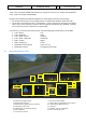
A318/319/320/321 Profesional 4. Flight Preparation: 4.1 Fuel and Payload Planning: Step-By-Step Tutorial Vol 6 06-01- 21 11. Dezember 2018 A planner for passengers, cargo and fuel is included in this package. You can find that via the windows startmenu. Please start the Fuel- and Payload-Planner and it will open in “Simple Mode”.
A318/319/320/321 Profesional Step-By-Step Tutorial Vol 6 06-01- 22 11. Dezember 2018 might be small differences between the values the “Fuel- and Payload-Planner” and P3D is stating after loading. For example: A319: Empty weight Payload Zero Fuel Weight Fuel Gross Weight 39.725 kg 8.921 kg 48.646 kg 6.862 kg 55.508 kg A320: Empty weight Payload Zero Fuel Weight Fuel Gross Weight 41.243 kg 8.921 kg 50.164 kg 7.615 kg 57.
A318/319/320/321 Profesional Step-By-Step Tutorial Vol 6 06-01- 23 11. Dezember 2018 To use the CHECKLIST and the COPILOT function it is necessary to load one of the menu – states. You access this menu via the Settings MCDU Main Menu by selecting ACFT STATE. Please load COLD DARK STATE. In real life most likely the maintenance would have prepared the aircraft already before the flight crew arrives, so TURN AROUND STATE could also be a realistic startup state.
A318/319/320/321 Profesional 4.5 Step-By-Step Tutorial Vol 6 06-01- 24 11. Dezember 2018 GROUND SERVICES – Ground Services Menu Ground Services You access the menu via the Settings MCDU Main Menu by selecting GND SERVICES. The menu is available only if the Wheel Chocks are SET or if the Parking Brake is ON (e. g. the aircraft now can park without Parking Brakes set to ON).
A318/319/320/321 Profesional 4.6.1 Step-By-Step Tutorial Vol 6 06-01- 25 11. Dezember 2018 OPTIONS - SOUND Sounds Configuration Menu CABIN CREW Background sounds by the purser like “Captain, all passengers are on board and the cabin is secured” FLIGHT CREW Background sounds by the flight crew like browsing in manuals, sneezing etc. ATC Background sounds from Air Traffic Controllers – instructions to other planes.
A318/319/320/321 Profesional Step-By-Step Tutorial Vol 6 06-01- 26 11. Dezember 2018 VOLUME Volume Configuration Menu Various sound volumes can be adjusted as required. Just enter the required value into the scratchpad and push the appropriate LSK. To set all values back to the original values please use “DEFAULT”. 4.6.2 OPTIONS - VIEWS View Configuration Menu VIEW SYSTEM The VIEW OPTION can be completely disabled so that there are no interferences for users who use TrackIR and EZDOC.
A318/319/320/321 Profesional Step-By-Step Tutorial Vol 6 06-01- 27 11. Dezember 2018 VC Panel Bar (day and night version) The VC-mode bar can be closed or opened again clicking on the “grey” triangle left and right on the bar. The views 11 to 17 can be accessed using the mouse wheel. To access the ADIRS view just select the Overhead view and then use the right mouse button.
A318/319/320/321 Profesional Step-By-Step Tutorial Vol 6 06-01- 28 11. Dezember 2018 WINGVIEW BAR The bar can be either displayed horizontal or vertical on the right upper corner of the screen. There are in total 10 different views available (1 to 6 please see below). The views 7 to 10 can be accessed by going with the mouse to the respective view then using the mouse wheel and clicking on it.
A318/319/320/321 Profesional Step-By-Step Tutorial Vol 6 06-01- 29 11. Dezember 2018 • If only “Checklist” is chosen, then the duties of the copilot must be handled manually by the user. In this case the Copilot just reads the checklist items and waits until the correct settings are made - before passing on to the next item. If settings are not made or are not correct the item is constantly repeated. Certain items can also be skipped by using the SKIP ITEM function (see chapter 4.8).
A318/319/320/321 Profesional Step-By-Step Tutorial Vol 6 06-01- 30 11. Dezember 2018 If selected the copilot checks the speed limit of 250 knots (below 10.000 feet) and if this limit is exceeded, the copilot automatically (using the speed brakes) reduces the speed to 250 knots. This function works without any calls and in “Managed” as well as in “Selected” speed mode. 250 Knots LIMITER If selected the copilot checks the speed limit of 250 knots (below 10.
A318/319/320/321 Profesional Vol Step-By-Step Tutorial 06-01- 31 11. Dezember 2018 6 TILLER The Tiller option allows you to de-activate the use of a standard Throttle 3 axis to control the tiller. On some machines this axis is not available or already in use then set this option to OFF. AUTO RUDDER Setting Auto rudder in your P3D settings to ON you also need to set this in the Settings MCDU to ON. It disables the A318/319/320/321 fly by wire function on the ground.
A318/319/320/321 Profesional Step-By-Step Tutorial Vol 6 06-01- 32 11. Dezember 2018 Load/Fuel Menu after INIT LOADSHEET Load Process If the loading process can be started the respective item is marked in “orange”. There are two ways to load pax, cargo and fuel to the plane. INSTANT = Just push LSK4R and pax, cargo and fuel are immediately loaded whereas using LSK1-3R the loading process takes some time like in the real world. The loading progress can be checked by looking at the ACT values.
A318/319/320/321 Profesional • Vol Step-By-Step Tutorial 6 06-01- 33 11. Dezember 2018 The COCKPIT PREP checklist should be started (if blinking in orange) by clicking on the respective line selection key = LSK3L. If it is marked in green (as on the picture above) it means it is already active. Additionally, a solution to skip a checklist item (if the copilot is not used) has been implemented (MCDU CHECKLIST PAGE A LSK2L).
A318/319/320/321 Profesional Step-By-Step Tutorial Vol 6 06-01- 34 11. Dezember 2018 The feature will make it possible for to people to connect to each other and act as Captain and FO’s (Or PF and PM). Details to this feature you will find in Vol 1 in chapter “Connected Flight Deck”. It is not used in the StepbyStep flight. 4.10 Voice packs for PF and PM For the checklists there will be various voice packs for the Pilot Flying as well as the Pilot Monitoring available . 4.
A318/319/320/321 Profesional Step-By-Step Tutorial 5. Tutorial Flight / Checklist and Procedures: 5.1 Basic Information - Setup Vol 6 06-01- 35 11. Dezember 2018 This tutorial flight describes all the phases of a flight from Frankfurt to London, from the “COLD DARK” situation in Frankfurt to the landing at London, parking and securing the aircraft.
A318/319/320/321 Profesional 5.2 Vol Step-By-Step Tutorial 6 06-01- 36 11. Dezember 2018 Basic Preparation Procedure (aircraft in COLD DARK state) BASIC PREPARATION PROCEDURE NO. 1 2 3 4 5 6 7 8 9 10 11 12 13 14 16 17 PANEL TYP PART (Name) FUEL PLANNER Settings MCDU OVERHEAD OVERHEAD OVERHEAD MAIN PANEL MAIN PANEL ECAM (various) Settings MCDU Settings MCDU Settings MCDU Settigns MCDU Settings MCDU Settings MCDU Settings MCDU ADV. METH. MAIN MENU ELEC ELEC EXT.
A318/319/320/321 Profesional 2. 5.3 Step-By-Step Tutorial Vol 06-01- 37 11. Dezember 2018 6 Load to Plane: Conditions to use these functions (except LOAD INSTANT) are: • All Load Requests: Engines = off and parking brakes or chocks are set • Pax boarding: Front or aft door is open • Cargo: Both cargo doors are open For details please see chapter 4.7 Cockpit Preparation COCKPIT PREPARATION NO. PANEL TYP PART (Name) 18 19 20 21 Settings MCDU OVERHEAD OVERHEAD OVERHEAD MAIN MENU ELEC ELEC EXT.
A318/319/320/321 Profesional GSX 5.4 Vol Step-By-Step Tutorial 6 06-01- 38 11. Dezember 2018 The loaded “COLD DARK” aircraft state is with parking brakes = OFF and chocks = SET (parking brakes are normally OFF to cool down the brakes) and is you use the GSX “4 – Request Boarding” option it should start with these conditions. FMGS / MCDU – Data Insertion Always use the following sequence for the data insertion into the MCDU: INIT A page, F-PLN, RAD NAV, INIT B page, PERF = IFRIP.
A318/319/320/321 Profesional Step-By-Step Tutorial Vol 6 06-01- 39 11. Dezember 2018 work, if a weather addon is used, that provide correct wind data for the waypoints or an overall TRIP WIND information. The Wind data for the waypoints can be entered manually via the WIND page or by using the WIND uplink function. The system will read the uplink WIND data from one of the following locations. ActiveSky Users: "C:\Users\USERNAME\AppData\Roaming\Hifi\AS_P3Dv4\Weather\activeflightplanwx.
A318/319/320/321 Profesional • • Step-By-Step Tutorial Vol 6 06-01- 40 11. Dezember 2018 Browse (use the button with arrow showing up) and look for lines showing F-PLAN-DISCONTINUITY If there is one, push the button CLR (check that CLR actually shows) and then the LSK L beside F-PLAN-DISCONTUNUITY Pseudowaypoints like the (T/C), (T/D) or (DECEL) points are at this stage not yet calculated by the MCDU since the weights are still to be initialized later.
A318/319/320/321 Profesional Vol Step-By-Step Tutorial 06-01- 41 11. Dezember 2018 6 22. FLEX TO: The value is automatically calculated and displayed based on the selected flaps setting for takeoff. If you want to change the value, just overwrite the content of this field. Because we will use Flaps 1 and the runway at EDDF is quite long a very high FLEX value is automatically calculated e. g. 67° is proposed. 23.
A318/319/320/321 Profesional 85 86 87 88 89 90 91 92 31. 32. 33. 34. 35. 5.7 OVERHEAD PEDESTAL PEDESTAL MCDU2 MCDU2 EFIS PEDESTAL OVERHEAD SIGNS THR LEVER P. BRAKE MAIN MENU MAIN MENU AP SETTING XPDR EXT. LIGHTS Vol Step-By-Step Tutorial 12 4 7 GND SERV. GND SERV. 2 9 SEAT BELT SIGNS / NO SMOKING = ON LEVERS PARKING BRAKE TRAFFIC CONES WHEEL CHOCKS BARO REF TRANSPONDER BEACON 06-01- 42 11.
A318/319/320/321 Profesional 36. 37. 38. 39. 40. 41. 42. Vol Step-By-Step Tutorial 6 06-01- 43 11. Dezember 2018 Taxiway Distance and Pushback Direction: After the checklist has been started automatically the following 2D MCDU menu opens Please set the distance to the taxiway (using LSK 3L or LSK 4L) as well as the pushback. To set the correct value you also can use the mouse scroll wheel. The feature uses the P3D basic pushback function and is it a little bit "enhanced".
A318/319/320/321 Profesional Vol Step-By-Step Tutorial 06-01- 44 11. Dezember 2018 6 CFM engines spool up to around N” 22% and then light up and produce an EGT rise. But if IAE engines are installed observe the EGT after 30 sec. because IAE implemented an 30 sec "blow through" / dry crank sequence to get rid of any remaining fuel/oil before starting the actual engine start sequence. 5.8 After Engine Start AFTER ENGINE START PANEL NO.
A318/319/320/321 Profesional 149 150 151 48. PEDESTAL EFIS PEDESTAL WXR FD / ILS TRANSPOND. Step-By-Step Tutorial 11 3 9 Vol SET system to 1 (ON) and knob to WX-T FD ATC CODE 06-01- 45 11. Dezember 2018 6 CoP SET CHECK ON CONFIRM / SET Checklist complete If ATC is used THRUST LEVERS: Set thrust levers to the manual range. Around 35 % N1 (EWD) should be enough to start the aircraft moving. Then set the thrust levers back to ZERO. Taxiing should be operated at 20 knots, with 10 knots during turns.
A318/319/320/321 Profesional Step-By-Step Tutorial Vol 06-01- 46 11. Dezember 2018 6 Taxichart EDDF B47 to Runway 18 5.10 Before Takeoff BEFORE TAKEOFF NO. PANEL ACTION TYP PART (Name) PART (No.) OVERHEAD ECAM MAIN PANEL PEDESTAL PEDESTAL OVERHEAD EXT. LIGHTS WHEEL PAGE BRAKE FAN ENGINE TCAS EXT. LIGHTS 9 1 11 5 10 9 PEDESTAL MAIN PANEL PEDESTAL PEDESTAL WXR N/SKID NW RADIO RADIO 11 10 1 1 152 153 154 155 156 157 158 159 160 161 162 163 143. 144. 145. 146.
A318/319/320/321 Profesional 147. Step-By-Step Tutorial Vol 6 06-01- 47 11. Dezember 2018 Approach Path Clear: Look left and right and assure that the runway is clear. Then enter the runway 18 for takeoff.
A318/319/320/321 Profesional Vol Step-By-Step Tutorial 06-01- 48 11. Dezember 2018 6 5.11 Takeoff (Part 1) TAKEOFF – Part 1 NO 164 165 148. PANEL ACTION TYP PART (Name) PART (No.
A318/319/320/321 Profesional Vol Step-By-Step Tutorial 06-01- 49 11. Dezember 2018 6 If it is necessary to reject the takeoff please just draw the thrust levers back to IDLE and set the reversers to MAX (by using F2 from the keyboard). Currently there is no special CL after “Rejected Takeoff”. In such cases please load the TAXI STATE (chapter of this manual) and start from there. 5.13 Takeoff (Part 2) TAKEOFF – Part 2 NO. 166 167 168 169 170 171 172 173 174 175 176 177 178 179 180 181 182 183 150.
A318/319/320/321 Profesional Vol Step-By-Step Tutorial 06-01- 50 11. Dezember 2018 6 Flight Director Flight Director: During takeoff XX. 152. 153. 154. 155. 156. 157. e. Shortly after takeoff the joystick position indicator and the runway yaw bar on the Attitude Indicator will disappear and Flight Director Indicator will show up (please see picture above). A.FLOOR: If you are flying with a too high Angle of Attack automatically the Alpha Floor mode (Display = A.
A318/319/320/321 Profesional Step-By-Step Tutorial EDDF – Runway 18 – SOBRA 1L SID Chart EDDF – Runway 18 – SOBRA 1L Procedural Description Vol 6 06-01- 51 11.
A318/319/320/321 Profesional Vol Step-By-Step Tutorial 06-01- 52 11. Dezember 2018 6 5.15 Climb CLIMB NO. PANEL PART (Name) TYP ACTION PART (No.) PF (PILOT FLYING) 199 CLIMB CHECKLIST 200 201 202 203 204 205 At 10.000 feet 158. 159. OVERHEAD FCU EXT. LIGHTS ALTITUDE 9 3 GL.SH /EFIS A PRESSURE 13 / 2 LANDING LIGHTS Cruise Altitude At Transition Altitude BARO REF to STD REMARK PM (PILOT MONITORING) Start Checklist / Co-Pilot - if selected “Passing 10.
A318/319/320/321 Profesional Vol Step-By-Step Tutorial 06-01- 53 11. Dezember 2018 6 5.16 Cruise CRUISE NO. 206 207 208 209 210 211 212 213 214 162. PANEL ACTION TYP PART (Name) PART (No.) PEDESTAL OVERHEAD TCAS SIGNS 10 11 PEDESTAL MCDU MCDU MCDU OVERHEAD ECAM Var.
A318/319/320/321 Profesional Vol Step-By-Step Tutorial 6 06-01- 54 11. Dezember 2018 Likewise, when you reach the Step Climb point it will not climb automatically. You then need to turn the FCU altitude up to the new altitude and push the ALT button to initiate the Step Climb. If you have any scheduled Step Climbs in your flight plan you can also enter the altitude/waypoint to tell the that you will do a Step Climb exactly at this waypoint.
A318/319/320/321 Profesional Vol Step-By-Step Tutorial 06-01- 55 11. Dezember 2018 6 MCDU – PERF – APPR page (A319 and A320) 164. 165. 166. 167. 168. QNH; TEMP; MAG WIND: Enter data (for arrival airport EGLL) TRANSITION LEVEL: (TRANS FL) for EGLL = FL070 (In real life determined by ATC, we will use Transition Altitude plus 1000ft here which would be the correct TL for our weather conditions) BARO – DA (decision altitude): According to the chart for EGLL ILS27L it is a CAT1 ILS approach.
A318/319/320/321 Profesional 172. Vol Step-By-Step Tutorial 06-01- 56 11. Dezember 2018 6 BARO REF: As we are flying higher than the “transition altitude” it should already be set to “Standard” i.e. nothing has to be done. EGLL Chart – STAR LAM 3A/TAWNY 3A 5.19 Descent DESCENT NO. 229 230 231 232 233 234 235 236 237 238 239 240 173. 174. PANEL ACTION TYP PART (Name) PART (No.
A318/319/320/321 Profesional Step-By-Step Tutorial Vol 6 06-01- 57 11. Dezember 2018 T/D = 34.000 Feet Top of Descent – Initiate descent 175. At 10.000 feet: As soon as the altitude of 10.000 feet is reached the speed restriction of 250 knots becomes valid. The aircraft will start to reduce its speed in order to reach 250kt at FL100. The actual Deceleration point will therefore be slightly earlier than FL100 to indicate where it will start to slow down. 10.
A318/319/320/321 Profesional Vol Step-By-Step Tutorial 06-01- 58 11. Dezember 2018 6 5.20 Approach APPROACH N O. 241 242 243 244 245 246 247 248 249 250 251 252 177. 178. 179. 180. 181. PANEL ACTION TYP PART (Name) PART (No.) ECAM ECAM 1 OVERHEAD MCDU EFIS OVERHEAD SIGNS PROG A.PRESSURE EXT.
A318/319/320/321 Profesional Vol Step-By-Step Tutorial 6 06-01- 59 11. Dezember 2018 Chart ILS 27L London Heathrow Green Dot Speed SSpeed FSpeed Vapp Speed Speeds “Green Dot”, S, F and Vapp on PFD 5.21 Final There are two main modes for the approach: Using “Managed Speed” or “Selected Speed (manually)”. Our Checklist- and Copilot-Function uses the “Managed Speed” mode.
A318/319/320/321 Profesional Vol Step-By-Step Tutorial 06-01- 60 11. Dezember 2018 6 FINAL NO. PANEL ACTION REMARK TYP PART (Name) 254 MCDU PERF 255 MAIN PANEL PFD 1 CALL: LOCALIZER ALIVE 2569 FCU APPR 6 APPR PUSH 257 MAIN PANEL PFD 1 LOCALIZER CAPTURED CHECK 241 MAIN PANEL SELECT CoP P3D: F7 PART (No.
A318/319/320/321 Profesional Step-By-Step Tutorial Vol 6 06-01- 61 11. Dezember 2018 Deceleration Pseudo Waypoint Deceleration Point 183. 184. 185. • LOC Alive: During the final turn the localizer becomes “alive” and this will be confirmed by a PM call “LOCALIZER ALIVE”. The conditions for this call are: The angle to the runway must be smaller than 90 ° and the Approach, Landing as well as BaroCheck are not active.
A318/319/320/321 Profesional 189. 190. 191. 192. Step-By-Step Tutorial Vol 6 06-01- 62 11. Dezember 2018 Some general information on the use of speed brakes: Normally you can use them whenever wanted. But there are some SOP things which must be considered. The first one has to do with high altitude flying (FL300 and higher). You cannot yank them to their full position at once. You must be smooth as to not disrupt the airflow to sudden.
A318/319/320/321 Profesional Step-By-Step Tutorial Vol 6 06-01- 63 11. Dezember 2018 s Glideslope Localizer PFD – Glidescope captured - Vertical and lateral glide path 193. 194. 195. 196. The middle of both fields shows the vertical and lateral position of the aircraft whereas the magenta rhombus shows the actual position on the glide path. This means that during the approach both rhombuses are moving to the center.
A318/319/320/321 Profesional Vol Step-By-Step Tutorial 6 06-01- 64 11. Dezember 2018 • Speed below 250 knots If the copilot function is set to ON the highest value is automatically inserted using the MCDU FPLAN data. The value will be entered by the copilot in visible steps (with sound) and considering the 100 and 1000 switch. Some values like 3.490 feet cannot be entered so the next possible higher value which means for 3.490 = 3.500 must be or are entered.
A318/319/320/321 Profesional 205. 206. 207. 208. 209. 210. 211. Step-By-Step Tutorial Vol 6 06-01- 65 11. Dezember 2018 Autopilot: Because EGLL ILS 04L is ILS CAT1 we are not allowed to use “AUTOLAND” and must disconnect the autopilot at latest at the decision altitude of 210 feet. Some airlines require that if no AP is used also the ATHR has to be switched off. LAND and FLARE mode: As the aircraft gets closer to the ground the LAND mode engages, then the FLARE mode.
A318/319/320/321 Profesional Vol Step-By-Step Tutorial 06-01- 66 11. Dezember 2018 6 GO AROUND NO. A B C D E F G H I J K L M N O P A. B. I. J. K. L. M. O. P. PANEL ACTION TYP PART (Name) PART (No.) PF (PILOT FLYING) PM (PILOT MONITORING) PEDESTAL PEDESTAL THR LEVER FLAPS 4 8 GA thrust is set “GO AROUND FLAPS” MAIN PANEL MAIN PANEL PEDESTAL OVERHEAD MAIN PANEL GEAR GEAR SPEED-BR. EXT.
A318/319/320/321 Profesional Step-By-Step Tutorial Vol 6 06-01- 67 11. Dezember 2018 Descent or Climb-to-Altitude On the Infobar you will see the following message: CHANGE FCU ALT FOR NEW APPROACH OR START APPROACH CL (MCDU OR KEY 1). ND – G/A flight path for LFMN ILS04L Before reaching NERAS we will enter a holding into the F-PLAN to wait for further instructions from ATC. • MCDU FPLAN: Scroll to NERAS (should be at the beginning e. g. before the FPLAN DISCONTINUITY) and push the respective LSK L.
A318/319/320/321 Profesional Step-By-Step Tutorial Vol 6 06-01- 68 11. Dezember 2018 Now there are two options to continue the flight: A. Another attempt to land at LFMN ILS04L • Only the FINAL waypoints for EGLL ILS04L (NI77 and NI51) have automatically been added to the FPLAN. • But we are advised to use TRANS/VIA “NERAS” again for our approach. So please push LSK6L, then ARRIVAL LSK1R and using LSK2L (VIA) select NERAS.
A318/319/320/321 Profesional Vol Step-By-Step Tutorial 06-01- 69 11. Dezember 2018 6 Back to our flight at Heathrow. As in the “real” there are no ALT/SPD PREDICTIONS available in GA phase. Also, there is no DECEL point calculated and symbol displayed on the ND during GA phase. The APPR PHASE (MCDU – PERF - APPR) must be manually activated as well as previously the APPROACH CL (MCDU or Key 1).
A318/319/320/321 Profesional Vol Step-By-Step Tutorial 06-01- 70 11. Dezember 2018 6 5.25 Parking PARKING NO. 319 320 321 322 323 324 325 326 327 328 329 330 331 332 333 334 335 328 329 PANEL ACTION REMARK TYP PART (Name) PART (No.) PF (PILOT FLYING) PM (PILOT MONITORING) PEDESTAL OVERHEAD PEDESTAL PEDESTAL PEDESTAL Settings MCDU PEDESTAL OVERHEAD OVERHEAD OVERHEAD OVERHEAD RADIO ANTI-ICE RADIO P.
A318/319/320/321 Profesional Step-By-Step Tutorial Overhead Panel before switching OFF both batteries Vol 6 06-01- 71 11.
A318/319/320/321 Profesional 6. Step-By-Step Tutorial Vol 6 06-01- 72 11. Dezember 2018 Vector Approach using DIR TO and RADIAL IN This part of the tutorial uses also the flightplan LOWIEGLL01 (Innsbruck to Nice) but covers only the descent from cruise level and the vector approach into Nice = EGLL 04L. It is mainly based on input from Frank “The Dude” (a RWpilot) how a RW vector approach is flown into EGLL ILS 04L.
A318/319/320/321 Profesional Step-By-Step Tutorial Vol 6 06-01- 73 11. Dezember 2018 Because we are at FL310 this means a descent of 14000’ equivalent to app. 42 NM (1000’ descent every 3 miles at a V/S of -2500). Adding some “reserve” we should therefore start our descent app. 15 NM before ENOBA. 6.1 Prepare the MCDU PERF APPR page MCDU PERF APPR page 6.2 20 NM before ENOBA manually start the DESCENT PREPARATION CL Start of DESC PREP CL 6.3 6.4 Set the FCU ALT to 17000’.
A318/319/320/321 Profesional Step-By-Step Tutorial Vol 6 06-01- 74 11. Dezember 2018 Reaching new FL170 before BORDI Reaching BORDI we get further ATC instructions o ATC – AUA319 Fly DIR TO PIRAM, descend FL080 - reach latest at PIRAM o PM – AUA319 DIR TO PIRAM, descend FL080 - reach latest at PIRAM 6.6 6.7 6.8 Set the FCU ALT to 8000’.
A318/319/320/321 Profesional Step-By-Step Tutorial Vol 6 ND after passing PIRAM 6.10 Transition Altitude = 5.000’ At NERAS o ATC - AUA319 turn right HDG 260 remain FL040, radar vectors ILS runway 04L o PM - AUA319, turning right HDG 260 FL040 6.11 PF pulls HDG knob on FCU and selects HDG 260 6.12 PF selects MCDU / DIR TO= NI122 (= FAP) and RADIAL IN 224 (044° plus 180°) Selecting DIR TO and RADIAL IN ND flight path after DIR TO and RADIAL IN 6.
A318/319/320/321 Profesional Step-By-Step Tutorial Vol 6 06-01- 76 11. Dezember 2018 ND flight path before changing HDG 350° 6.14 PF selects HDG 350 on FCU ND flight path after changing HDG 350° 6.15 Arm the FCU APPR mode by pushing the APPR knob. 6.16 When the approach mode is armed also switch on the second AP. ND flight path after arming APPR mode 6.
A318/319/320/321 Profesional Step-By-Step Tutorial Vol 6 06-01- 77 11. Dezember 2018 6.18 The plane turns into the RADIAL IN course Approaching RADIAL IN 6.
A318/319/320/321 Profesional 7. 7.1 Step-By-Step Tutorial Vol 6 06-01- 78 11. Dezember 2018 Non Precision Approach (NPA) Introduction This part is meant to serve as a simple Non-Precision Approach Guide to pilots, unfamiliar with all the tools the provides for such an approach. This part of the guide is written by Joshua (developer) and a real world A320 pilot. But still there might be some deviations from Real World Procedures.
A318/319/320/321 Profesional Step-By-Step Tutorial Vol 6 06-01- 79 11. Dezember 2018 should blink in amber. To change now to the Final APP Mode the following must be given: • Before the VIP (vertical interception point) the plane must be vertical as well as lateral stabilized (in our tutorial flight at GAR09). • The Approach Phase should be activated (happens automatically when passing the „Deceleration Points“ which is app.
A318/319/320/321 Profesional Step-By-Step Tutorial Vol 6 06-01- 80 11. Dezember 2018 10.000 Fuß = IAF 2.000 Fuß = MAPT GAR09 = FAF / VIP STAR chart (PITAS2J) for LGKR 2.
A318/319/320/321 Profesional 7.6 Step-By-Step Tutorial Vol 6 06-01- 81 11. Dezember 2018 Approach Brief Vertical information for Rwy35-y for LGKR This is the vertical information of the IAC Chart. Take note of the three things circled on the chart, namely IAF, FAF or VIP, and MAPT. The approach is divided into three following sections: 1. IAF is the Initial Approach Fix, which denotes the start of Initial Approach. 2.
A318/319/320/321 Profesional Vol Step-By-Step Tutorial 6 06-01- 82 11. Dezember 2018 Flight Path Vector and Flight Path Director 2 7.8 Descent Preparation and Descent • Fill in the MCDU PERF Approach Page as follows: QNH, TEMP and MAG/WIND are according to the expected METAR data (6.3). The transition altitude for LGKR is 5.000 feet and the BARO = MDA (minimum descent altitude) according to the chart = 2.000 feet. MCDU PERF APPR page • • Set the “to descent to altitude” on the FCU to 2.
A318/319/320/321 Profesional Step-By-Step Tutorial Vol 6 06-01- 83 11. Dezember 2018 Descent Flight Path 7.9 Initial Approach Fix (IAF) The IAF for LGKR VOR RWY 35-y is below 10.000 feet (please see chart – picture 67). At IAF you should already have: 1. Filled in the MCDU Approach Page (6.8). 2. Already briefed on the Missed Approach Procedures. 3. Be cleared by ATC for the approach When passing the IAF, you should begin to setup your displays to give you the necessary information for your approach.
A318/319/320/321 Profesional ▪ Step-By-Step Tutorial Vol 6 06-01- 84 11. Dezember 2018 Switch the ND to Rose Mode = Rose VOR or to Arc Mode and set range to an appropriate range. Pressing the APPR button will arm the FINAL Mode on the MCDU which will provide FINAL APP vertical and lateral guidance. After passing 10.000 feet = IAF 7.10 Deceleration Point You will reach the DECEL point app.
A318/319/320/321 Profesional Step-By-Step Tutorial Vol 6 06-01- 85 11. Dezember 2018 After Passing DECEL, • APPR Phase activates on the MCDU and the VDEV Scale replaces the VDEV magenta dot. • We highly recommend using the speed brakes after activating the APPR PHASE until the magenta square on the VDEV scale is in the middle of the scale as shown in the picture above. • ALT and NAV FMA replaced by FINAL APP FMA.
A318/319/320/321 Profesional 7.11 Step-By-Step Tutorial Vol 6 06-01- 86 11. Dezember 2018 Final Approach Fix (FAF) The FAF for LGKR VOR RWY 35-y is at GAR09 (please see chart – picture 80). Before FAF = GAR09 Passing GAR09 = FAF After Passing FAF the plane should start to descent following the V/DEV flight path. • • • • • Check that FINAL APP is green on the FMA. Check A/THR Mode is SPEED Mode. Monitor Position and Flight Path is within acceptable limits. ECAM LDG Memo should be green.
A318/319/320/321 Profesional 7.12 Step-By-Step Tutorial Vol 6 06-01- 87 11. Dezember 2018 Minimum Decision Altitude (MDA) At MAP/MDA (which is set to 2.000 feet) • Check LDG MEMO is all green. • Approach is stable. • Visual with runway. If those conditions are met the captain will announce "LANDING". • Disconnect AP and proceed to fly manually • Turn FD off • Set TRK on the FCU to runway track (=345). Failure to disconnect AP by MDA will result in automatic AP disconnection at MDA-50 ft.
A318/319/320/321 Profesional 8. A318 - Steep Approach 8.1 Introduction Step-By-Step Tutorial Vol 6 06-01- 88 11. Dezember 2018 This part is meant to serve as a simple A318 Steep Approach Guide to pilots, unfamiliar with all the tools the provides for such an approach. This part of the guide is edited by a real world A 320 pilot. But still there might be some deviations from Real World Procedures. MANAGED MODE We are using for this “Managed Mode”. 8.
A318/319/320/321 Profesional Step-By-Step Tutorial Vol 6 06-01- 89 11. Dezember 2018 Flight path EDDH - EGLC STAR chart (SPEA1B) for EGLC The approach is divided into three following sections: • IAF is the Initial Approach Fix, which denotes the start of Initial Approach. • FAP is the Final Approach Point (for ILS landings) and VIP (Vertical Interception Point), which denotes the start of Final Approach.
A318/319/320/321 Profesional 8.6 Vol Step-By-Step Tutorial 6 06-01- 90 11. Dezember 2018 MCDU PERF APPR PAGE MCDU PERF APPR PAGE NO. PANEL ACTION REMARK TYP PART (Name) PART (No.) PF (PILOT FLYING) PM (PILOT MONITORING) 1 MCDU PERF APPR QNH, TEMP, MAG WIND ENTER DATA 2 MCDU PERF APPR TRANS ALT ENTER DATA = 6000 3 MCDU PERF APPR BARO / RADIO ENTER DATA = BARO 550 4 MCDU PERF APPR VAPP ENTER DATA 5 MCDU PERF APPR LDG CONF CHECK MCDU PERF APPR page 1. 2. 3. 4.
A318/319/320/321 Profesional 8.7 Vol Step-By-Step Tutorial 06-01- 91 11. Dezember 2018 6 Descent Preparation DESCENT PREPARATION NO. PANEL PART (Name) TYP ACTION PART (No.) 6 PF (PILOT FLYING) REMARK PM (PILOT MONITORING) 1 min after CRZ level has been reached 7 Start Checklist / Co-Pilot - if selected SEAT BELTS = ON or AUTO CHECK and set to ON 8 OVERHEAD ANTI-ICE 8 ANTI ICE = OFF CHECK 9 PEDESTAL RADIO 1 LANDING INFORMATION RECEIVED 10 EFIS A.
A318/319/320/321 Profesional Vol Step-By-Step Tutorial 06-01- 92 11. Dezember 2018 6 UPPER ECAM – Steep Approach Button = ON 12. 8.
A318/319/320/321 Profesional Step-By-Step Tutorial Vol 6 06-01- 93 11. Dezember 2018 T/D = 31.000 Feet Top of Descent – Initiate descent 23. At 10.000 feet: As soon as the altitude of 10.000 feet is reached the speed restriction of 250 knots becomes valid. Therefore the aircraft automatically reduces the target speed to 250 knots already at 11.000 feet app. 9 NM before TRIPO. 10.000 feet Deceleration Point ND: Deceleration Point The IAF (Initial Approach Fix) for EGLC RWY ILS27 is below 5.
A318/319/320/321 Profesional 24. 25. 27. Vol Step-By-Step Tutorial 06-01- 94 11. Dezember 2018 6 LS Pushbutton: If the button is used (normally when passing 10.000 feet) the “Vertical Glideslope” as well as the “Lateral Localizer” shows up on the PFD. The ND display shows ILS27 on top as soon as the remaining distance to destination is 250 NM or less. Transition Altitude: Setting up the MCDU PERF APPR page we set it to 6.000 feet for the approach (#2).
A318/319/320/321 Profesional 38 MCDU PROG 39 MAIN PANEL PFD 28. Vol Step-By-Step Tutorial 1 06-01- 95 11. Dezember 2018 6 NAV ACCURANCY MONITOR POSITIONING MONITOR Approach CL: The APPROACH CL now is available for manually start (MCDU2 CHECKLIST MENU = marked in orange) app. 10 NM before the DECEL pseudo waypoint and a message pops up on the INFOBAR showing the distance and explains the start options. It starts automatically app. 5 NM before DECEL pseudo waypoint.
A318/319/320/321 Profesional Vol Step-By-Step Tutorial 06-01- 96 11.
A318/319/320/321 Profesional Step-By-Step Tutorial Vol 6 06-01- 97 11. Dezember 2018 Deceleration Pseudo Waypoint Deceleration Point 42. 43. 44. 45. 46. 48. Green Dot Speed / CLEAN: After initiating the APPR Phase (#41) automatically the MCDU reduces the speed to “Green Dot Speed” (197 knots).
A318/319/320/321 Profesional 49. 50. 55. 56. 58. Step-By-Step Tutorial Vol 6 06-01- 98 11. Dezember 2018 APPR Button: Before passing LSR06 (you are already flying at LSR34) and after hearing the call “LOCALIZER ALIVE” = press the APPR button on the FCU. LOC Capture: The “capture” will be confirmed i.e. lateral path has been caught. Please note: If you are pushing the APPR button too early (before turning to LSR06/LSR34) it might happen that the plane captures the localizer in the wrong direction.
A318/319/320/321 Profesional Vol Step-By-Step Tutorial 6 06-01- 99 11. Dezember 2018 that it is never less than VLS + 5 or more than VLS +15. As a result, VAPP is increased above its minimum value for runway headwinds above 15 knots. VAPP correction is not increased further for headwinds exceeding 45 knots. No additions are made for gusts.
A318/319/320/321 Profesional 73. 74. 75. 76. 77. 78. 79. 81. 82. 86. Step-By-Step Tutorial Vol 6 06-01- 100 11. Dezember 2018 Go Around Altitude: Check if the GA has been set correctly according to #56. BARO – DA (decision altitude): Please also see #3 – for EGLC ILS 27 according to the charts = 550 feet. At an altitude of 650 feet there will be a call “100 ABOVE”.
A318/319/320/321 Profesional 9. 9.1 Step-By-Step Tutorial Vol 6 06-01- 101 11. Dezember 2018 Alternate Company Routes and Destinations Alternate Company Routes An alternate company route is a flightplan (company route) from the primary destination to an alternate destination. The format and the location where those flightplans are saved are identical with those of primary flightplans. For our tutorial we use as a primary flightplan EDDFLOWG01 e.g. from EDDF (Frankfurt/Germany) to LOWG (Graz/Austria).
A318/319/320/321 Profesional Step-By-Step Tutorial Vol 6 06-01- 102 11. Dezember 2018 Entering ALTN destination – step 3 Now the two flightplans are loaded and can be reviewed on the F-PLAN pages. The primary flightplan is displayed in “green” whereas the GA waypoints and the alternate flightplan are displayed in “blue. Both flightplans are separated by ------ END OF F-PLAN -------.
A318/319/320/321 Profesional Step-By-Step Tutorial Vol 6 06-01- 103 11. Dezember 2018 Enabling ALTN DEST – step 3 Enter NERDU into “NEXT WPT” and push LSK3R Entering NERDU as NEXT WPT after the revise point ALMER Automatically you are then back to the temporary flightplan page.
A318/319/320/321 Profesional Step-By-Step Tutorial Vol 6 06-01- 104 11. Dezember 2018 If another waypoint is entered after the revise point = ALMER and before the F-PLAN DISCONTINUITY (in our example = NERDU) and this waypoint is also part of the alternative company route then the flightplan collapses. E. g. all waypoint of the alternate company route until this waypoint (= NERDU) are automatically deleted.
A318/319/320/321 Profesional Step-By-Step Tutorial Vol 6 06-01- 105 11. Dezember 2018 Picture 2: Entering ALTN DEST = LOWW • As we will not use the existing ALTN CO RTE “LOWGLOWW01” please just go back to the INIT A page ( (=RETURN LSK 6L). Not using existing CO RTE • The INIT A page then looks as follows INIT A page with ALTN destination Now the two flightplans are loaded and can be reviewed on the F-PLAN pages.
A318/319/320/321 Profesional Step-By-Step Tutorial Vol 6 06-01- 106 11. Dezember 2018 Enabling ALTN DEST – step 1 Enable the alternate destination by pushing LSK 4L. Enabling ALTN DEST – step 2 Then the following screen opens: Enabling ALTN DEST – step 3 Go back to the F-Plan and use TMPY INSERT = LSK 6R. The alternate flightplan now becomes the active primary flightplan.
A318/319/320/321 Profesional Step-By-Step Tutorial Vol 6 06-01- 107 11. Dezember 2018 Active flight plan after enabling ALTN Select the ARRIVAL for LOWW (LSK 6L) = ILS16 – no STAR – but just transition for runway 16 = NER5L and insert the temporary flightplan (LSK 6R).
A318/319/320/321 Profesional Active F-PLAN EDDF - LOWW Step-By-Step Tutorial Vol 6 06-01- 108 11.
A318/319/320/321 Profesional Step-By-Step Tutorial Vol 6 06-01- 109 11. Dezember 2018 10. Tips and Tricks: 10.1 Adjusting views: If you want to adjust one of the various available views first open it e. g. it becomes the active window.
A318/319/320/321 Profesional • • Step-By-Step Tutorial Vol 6 06-01- 110 11. Dezember 2018 At the bottom of the page you will see the ACROBAT icon and the list of documents which are already available in ACROBAT. Use “ADD” to select this document (saved in your P3D folder under Aerosoft / A318_A319 (or A320_321) / Documentation) and it will be transferred to your iPad. Open ACROBAT and select “Documents”. Now this tutorial should be available and can be opened and used on your iPad. 10.
A318/319/320/321 Profesional Step-By-Step Tutorial 11. Appendix / Glossary: Abbreviation Description ABV ADF A/C AGL A.
A318/319/320/321 Profesional F-PLAN FQ GPU GPWS GS GW HDG hPa IAE ILS In Hg INIT KG IRS L/G LK LOC LSK MCDU MDA MKR N/W ND NDB (ADF) NM PERF PFD PPU PROG QNH PSI PTU RAD/NV RAAS RMP RTO RWY SD SEC SID SRS STAR STDBY SW TA TA/RA TAS T/C TCAS T/D TERR THR THR RED THRT THS TOGA TOW TRANS TRK UTC Step-By-Step Tutorial Flight Plan (MCDU Page) Fuel Quantity Ground Power Unit Ground Proximity Warning System Glide Slope Gross Weight Heading Air Pressure Unit of Measurement (hector Pascal) Int.
A318/319/320/321 Profesional V1 V2 V/S Vfe VHF Vls Vmax Vmo/Mmo VOR Vr XFR ZFW ZFWCG Step-By-Step Tutorial Speed at which takeoff cannot be aborted Minimum Takeoff Safety Speed Vertical Speed Maximum Flap Extended Speed Very High Frequency Minimum Safe Speed Maximum Operating Speed In Current Condition Maximum Operating Limit Speed Very High Frequency Omnirange Station Rotation Speed Transfer Zero Fuel Weight Zero Fuel Weight Centre of Gravity Vol 6 06-01- 113 11.
A318/319/320/321 Profesional Vol Step-By-Step Tutorial 06-01- 114 11. Dezember 2018 6 12. Checklists and Procedures A 319 CFM 12.1 Basic Preparation Procedure (aircraft in COLD DARK state) BASIC PREPARATION PROCEDURE NO. 1 2 3 4 5 6 7 8 9 10 11 12 13 14 15 16 16 PANEL TYP PART (Name) FUEL PLANNER Settings MCDU OVERHEAD OVERHEAD OVERHEAD MAIN PANEL MAIN PANEL ECAM PEDESTAL Settings MCDU Settings MCDU Settings MCDU Settings MCDU ADV. METH.
A318/319/320/321 Profesional 49 PEDESTAL RADIO Step-By-Step Tutorial 1 ATC CLEARANCE OBTAIN Vol 6 06-01- 115 11.
A318/319/320/321 Profesional Vol Step-By-Step Tutorial 06-01- 116 11. Dezember 2018 6 12.3 FMGS / MCDU – Data Insertion COCKPIT PREPARATION – FMGS/MCDU DATA INSERTION PANEL NO. 50 51 52 53 54 TYP ACTION PART (Name) PART (No.
A318/319/320/321 Profesional Vol Step-By-Step Tutorial 06-01- 117 11. Dezember 2018 6 12.6 Engine Start 12.6.1 Engine Start with Pushback ENGINE START – with pushback NO. 88 89 90 91 92 93 94 95 96 97 98 99 100 101 102 103 104 105 PANEL ACTION PART (Name) TYP Settings MCDU Settings MCDU Settings MCDU PART (No.
A318/319/320/321 Profesional Vol Step-By-Step Tutorial 06-01- 118 11. Dezember 2018 6 12.8 TAXI TAXI NO. PANEL ACTION REMARK TYP PART (Name) PART (No.) PF (PILOT FLYING) PM (PILOT MONITORING) 132 133 134 135 136 137 138 139 140 141 142 143 PEDESTAL PEDESTAL RADIO P. BRAKE 1 7 OBTAINED OFF OVERHEAD PEDESTAL EXT.
A318/319/320/321 Profesional Vol Step-By-Step Tutorial 06-01- 119 11. Dezember 2018 6 12.12 Takeoff (Part 2) TAKEOFF – Part 2 NO. 160 161 162 163 164 165 166 167 168 169 170 171 172 173 174 175 176 177 PANEL TYP PART (Name) ACTION PART (No.
A318/319/320/321 Profesional Vol Step-By-Step Tutorial 06-01- 120 11. Dezember 2018 6 12.16 MCDU PERF APPR page MCDU PERF APPR PAGE NO. 209 210 211 212 213 PANEL ACTION TYP PART (Name) PART (No.) PF (PILOT FLYING) PM (PILOT MONITORING) MCDU MCDU MCDU MCDU MCDU PERF PERF PERF PERF PERF APPR APPR APPR APPR APPR QNH, TEMP, MAG WIND TRANS ALT BARO / RADIO VAPP LDG CONF ENTER DATA ENTER DATA ENTER DATA CHECK CHECK PART (No.
A318/319/320/321 Profesional Vol Step-By-Step Tutorial 06-01- 121 11. Dezember 2018 6 12.20 Final FINAL NO. PANEL ACTION REMARK TYP PART (Name) 247 MCDU PERF 248 MAIN PANEL PFD 1 CALL: LOCALIZER ALIVE 2499 FCU APPR 6 APPR PUSH 250 MAIN PANEL PFD 1 LOCALIZER CAPTURED CHECK 241 MAIN PANEL SELECT CoP P3D: F7 PART (No.
A318/319/320/321 Profesional Vol Step-By-Step Tutorial 06-01- 122 11. Dezember 2018 6 12.22 Go Around GO AROUND NO. A B C D E F G H I J K L M N O P PANEL ACTION TYP PART (Name) PART (No.) PF (PILOT FLYING) PM (PILOT MONITORING) PEDESTAL PEDESTAL THR LEVER FLAPS 4 8 GA thrust is set “GO AROUND FLAPS” MAIN PANEL MAIN PANEL PEDESTAL OVERHEAD MAIN PANEL GEAR GEAR SPEED-BR. EXT.
A318/319/320/321 Profesional Vol Step-By-Step Tutorial 6 06-01- 123 11. Dezember 2018 12.25 Securing Aircraft SECURING AIRCRAFT NO. PANEL ACTION TYP PART (Name) PART (No.) PF (PILOT FLYING) PM (PILOT MONITORING) ADIRS EXT. LIGHTS SIGNS 9 11 ADIRS (1 + 2 + 3) NAV.