
User's Guide


Form #: OP_01_TM
Title: Aeronix Data Links – EDL Nano Products User Guide
Document Number: AE301628-001
Revision: B Date: 3 October 2019
Aeronix Proprietary
11
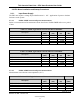
Table 2-11 OFDM T/R SW Timing
Marker
Time (us)
Description
t1
12 us
Minimum time from Tx Enable Active to start of Transmit Out
t2
0
Minimum time from Transmit Out Complete to Tx Enable Inactive
t3
80 us
Minimum Time from Rx Enable Active to Receive energy
t4
11 us
Minimum time from Receive Energy Complete to Rx Enable
Inactive
t5
10.5 us
Minimum switching time, ie minimum amount of Idle time before a
radio will switch between Rx and Tx state or Rx and Rx state
2.3.1. Tx Rx Enable 4 State (OFDM only)
External Tx and Rx control lines with 1.8V logic.
2.3.2. External GPIO 1 & 3
Not Used
2.3.3. Red and Green LED
The external Red and Green LEDs will give the user some basic status of the radios current state.
Green only LED on -> The NANO is in sync with another radio
Red only LED on -> The Nano’s RF is turned off via the software Tx/Rx enable/disable
setting.
Green and Red LED on (Yellow) -> The NANO RF is on, but NOT in sync with another
radio.
2.3.4. Tamper
Not Used
2.3.5. RF Output Power
The NANO output power will remain unchanged regardless of the RF environment. The NANO
output power is based on frequency and is calibrated per Radio Card. Each radio will have its
own calibration programmed and available for the user to view. Each NANO may vary from 1-2
dB of output power. See section 7.1 NANO output power for more information on determining
the output power measured on a particular frequency.
3. System Configuration
3.1. Aeronix GUI interface
This simple yet powerful GUI uses uncomplicated intuitive screens to allow the average user the
ability to: