
User's Guide


Form #: OP_01_TM
Title: Aeronix Data Links – EDL Nano Products User Guide
Document Number: AE301628-001
Revision: B Date: 3 October 2019
Aeronix Proprietary
10
2.3.5. Platform RS-232
Serial interface is for serial to serial communication. This interface is a RS-232 standard
interface. The debug port is configured as 8-N-1, the BAUD rate is configurable via the webgui
or SNMP. This interface is used to pass serial data from a BS serial port to one of its SS serial
port.
2.3.6. P1 Antenna Interface TxRx 1
The antenna interface is an SMA connector that provides both input and output RF signalling.
2.3.7. P2 Antenna Interface Rx 2
The antenna interface is an SMA connector that provides input RF signalling.
2.3.8. Tx Rx Enable
The Tx/Rx Enable is a three state condition. It requires an external pull-up resistor of 4.7 kilo
ohms to supply voltage V (customer determined with a max of 5V), see diagram below.
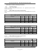
Figure 2-4 TR SW Timing
Table 2-10 GMSK 14 MHz T/R SW Timing
Marker
Time (us)
Description
t1
TBD
Minimum time from Tx Enable Active to start of Transmit Out
t2
TBD
Minimum time from Transmit Out Complete to Tx Enable Inactive
t3
TBD
Minimum Time from Rx Enable Active to Receive energy
t4
TBD
Minimum time from Receive Energy Complete to Rx Enable
Inactive
t5
TBD
Minimum switching time, ie minimum amount of Idle time before a
radio will switch between Rx and Tx state or Rx and Rx state
Tx
Rx
t1
t3 t4
0V (Tx)
V/2 (Rx)
V (Idle)
Rx Tx Enable
Tx Out
Rx Open
t2
t5