
User's Guide


Form #: OP_01_TM
Title: Aeronix Data Links – EDL Nano Products User Guide
Document Number: AE301628-001
Revision: B Date: 3 October 2019
Aeronix Proprietary
6
2.3. EDL Nano Physical I/O
The front panel of an EDL Nano is shown in the following figure. Indicated ports are described
below.
Figure 2-2 NANO RF Input/Output
The
back
panel
of an
EDL
Nano
is
shown
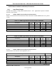
in the following figure. Indicated connectors are described below.
Table 2-6. Nano Hardware Interface
Connector
Description
EDL Connector
Mating Connector
P1
Tx/Rx1: Female SMA
connector connects to the
desired antenna
Male SMA
Female SMA
P2
Rx2: Female SMA connector
connects to the desired
antenna
Male SMA
Female SMA
P1: RF 1,
Tx/Rx
P2: RF 2,
Rx Only