
User Guide


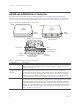
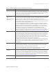
Table Of Contents

Chapter 1 Aerohive AP330 and AP350
8 Aerohive
AP330 AND AP350 PRODUCT OVERVIEW
The AP330 and AP350 models provide excellent throughput and coverage. The AP330 has internal
antennas, and the AP350 has detachable external antennas. You can see the hardware components on
the AP in Figure 1. Each component is described in Table 1 "AP330 and AP350 component descriptions".
Figure 1 AP330 and AP350 hardware components
Table 1 AP330 and AP350 component descriptions
Component Description
Status Indicator The status indicator conveys operational states for system power, firmware updates,
Ethernet and wireless interface activity, and major alarms. For details, see "Status
Indicator" on page 14.
2.4 and 5 GHz
RP-SMA connectors
(AP350)
You can connect up to six detachable single-band antennas to the male
802.11a/b/g/n RP-SMA (reverse polarity-subminiature version A) connectors.
Connect the antennas that have white ribbed rings and are labelled 2.4 GHz to
the connectors that are labelled
2.4 GHz. Connect the antennas that have gray
knurled rings and are labelled
5 GHz to the connectors that are labelled 5 GHz
and are encircled by a gray line. For details, see "Antennas" on page 14.
Console port You can access the CLI by making a serial connection to the RJ-45 console port.
The management station from which you connect to the device must have a VT100
emulation program, such as Tera Term Pro
©
(a free terminal emulator) or Hilgraeve
Hyperterminal
®
(provided with Windows
®
operating systems from Windows 95 to
Windows XP). The following are the serial connection settings: bits per second: 9600,
data bits: 8, parity: none, stop bits: 1, flow control: none. For details, see "Ethernet
and Console Ports" on page 10.
AP330
AP350
Status
indicator
RP-SMA connectors for 2.4 and
5 GHz antennas
AP330 and AP350 underside
(identical for both devices)
Reset
Security tab cavity
Device lock slot
Security
screw hole
USB port
10/100/1000
Mbps Ethernet ports
(PoE on ETH0)
Power
connector
Console port
Status
indicator