
User Guide
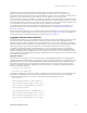
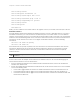
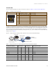
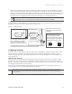

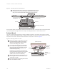
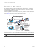
Table Of Contents

AP330 and AP350 User Guide 13
AP330 AND AP350 PRODUCT OVERVIEW
Console Port
The pin-to-signal mapping in the RJ-45 console port is shown in Table 2 "Console port pin assignments".
To make a serial connection between your management system and the device, you can use the console
cable that is available as an extra accessory. Insert the RJ-45 connector into the console port, and attach
the DB-9 connector to the serial (or COM) port on your management system. The management system must
have a VT100 terminal emulation program, such as Tera Term Pro
©
(a free terminal emulator) or Hilgraeve
Hyperterminal
®
(provided with Windows
®
operating systems). If you want to make your own serial cable and
adapter, refer to Figure 3.
Figure 3 Wiring details for making a serial cable with an RJ-45-to-Female DB-9 adapter
Table 2 Console port pin assignments
Console Port Pin SIgnal Direction
1 RTS (Request to Send) Output, unused
2 DTR (Data Terminal Ready) Output, unused
3
TXD (Transmitted Data) Output
4
Ground Ground
5
Ground Ground
6
RXD (Received Data) Input
7 DSR (Data Set Ready) Input, unused
8 CTS (Clear to Send) Input, unused
Because this is a console port, only pins 3, 4, 5, and 6 are currently in use.
Table 3 Wiring information for a serial cable with RJ-45-to-female DB-9 adapter
Console Port (AP340)
RJ-45 to RJ-45
rollover cable
RJ-45 to female
DB-9 adapter Management signal
Signal Pin Pin Pin DB-9 Pin Signal
RTS (Request to Send) 1 8 1 8 CTS (unused)
DTR (Data Terminal Ready) 2 7 2 6 DSR (unused)
TXD (Transmitted Data) 3 6 3 2 RXD
Ground 4 5 4 5 Ground
Ground 5 4 5 5 Ground
RXD (Received Data) 6 3 6 3 TXD
DSR (Data Set Ready) 7 2 7 4 DTR (unused)
CTS (Clear to Send) 8 1 8 7 RTS (unused)
- - - - 9 RI (Ring Indicator, unused)
CONSOLE
8 7 6 5 4 3 2 1
RJ-45 Console port
Rollover cable with
RJ-45 connectors
RJ-45-to-female
DB-9 adapter
Console port
COM port
(on back panel)
CONSOLE
Management system
AP121